A wind tunnel investigation of the helicopter vortex ring state boundary
-
摘要: 本文对直升机涡环状态边界进行了系统的分析与研究。首先,剖析了涡环状态事故的成因,阐述了其在飞行特性、旋翼性能、桨盘入流、涡系结构等方面的物理机制,指出涡环状态下安全隐患的主要诱因是桨尖涡受挤压形成集中涡,使桨盘面上诱导入流相对垂向来流占优,造成旋翼拉力负阻尼与性能损失,导致浮沉运动失稳。然后,对比了各类涡环状态边界的差异性和适用性,指出现有边界预测模型存在建模方式主观性强和试验数据离散度高的问题,并提出了改进思路。最后,设计并开展了模拟下降飞行的旋翼风洞试验。试验结果显示:涡环状态下出现了旋翼拉力负阻尼、拉力损失和功率沉陷现象,旋翼拉力损失最高达30%,旋翼产生维持机体重量拉力的需用功率约为悬停功率的 160%。以特情防范实践中关注的旋翼拉力负阻尼和拉力性能损失为指标,从试验结果中提取了涡环状态边界临界速度离散点。在涡环状态边界预测模型构建中区分水平来流、垂向来流和诱导入流对桨尖涡驱动作用的强弱,并计入不同前进比下动量理论的修正和桨尖涡运动阈值的差异,基于试验值采用最小二乘法确定了模型参数,建立了半经验化的涡环状态边界预测模型,模型预测结果与风洞试验结果吻合较好,且符合飞行试验规律。本文对认识涡环状态特情和预防涡环状态事故具有现实意义。Abstract: The helicopter vortex ring state boundary is systematically analyzed and studied in this paper. Firstly, the causes of vortex ring state accidents are analyzed, and the physical mechanisms in flight characteristics, rotor performance, rotor inflow, and vortex structure are expounded. The formation of concentrated vortex causes the induced inflow to dominate the vertical inflow on the rotor disk, causing negative damping of rotor thrust and loss of rotor performance, and as a result the instability of subsidence motion. Then, the differences and applicability of various vortex ring state boundaries are compared, the problems of the existing boundary prediction models with strong subjectivity in modeling methods and high dispersion of test data are concluded, and improvement ideas are proposed. Finally, on the basis of the above knowledge, a rotor wind tunnel test to simulate the descending flight was designed and carried out. The test results show that the rotor thrust negative damping, thrust loss and power subsidence phenomenon are presented in the vortex ring state, the rotor thrust loss is up to 30%, and the required power is about 160% of the hovering power when the rotor generates the same thrust as hover; using the negative damping of rotor thrust and the loss of thrust performance, which are concerned in the practice of flight emergency, as the defining index, the discrete points of the critical velocity at vortex ring state boundary are extracted from the test results; in the construction of the vortex ring state boundary model, the strength of the horizontal inflow, the vertical inflow and the induced inflow on the rotor tip vortex is distinguished, and the correction of the momentum theory under different advance ratios and the difference of the rotor tip vortex motion threshold are taken into account. On the basis of the model parameters determined by the least squares method based on the test values, a semi-empirical vortex ring state boundary prediction model is established, and the model is in good agreement with the wind tunnel test results and in line with the trend of flight test results.
-
Keywords:
- vortex ring state /
- helicopter /
- flight emergency /
- wind tunnel experiment /
- blade tip vortex
-
0 引言
目前,要求地面试验设备完全模拟高超声速飞行环境是非常困难的,在一个试验设备上进行所有环境的模拟试验更是不可能的。因此,需要研制多种试验设备,以满足高超声速试验需求[1-5]。
常规高超声速风洞主要模拟参数是马赫数和雷诺数[6],其他一些参数则主要通过高焓试验设备来模拟[7-8]。
在高超声速风洞运行中,气源不仅要维持风洞所必须达到的压力比,还需要满足雷诺数模拟的要求。一般来说,风洞的总压要足够高。如果风洞连续工作,高的压力比和高总压将使风洞消耗很大的动力,因而高超声速风洞多为暂冲式。
暂冲式常规高超声速风洞的运行方式是:气罐中的压缩空气经过加热系统达到所需温度,然后通过型面喷管,在试验段形成所需的高超声速流场,最后经由超声速扩散段升压后进入引射排气系统,排入大气,或经过冷却器进入真空系统,由真空泵系统排入大气。常规高超声速风洞一般加热温度在800K以下,主要是为了防止气流冷凝,不能真实模拟实际总温(马赫数6时达到1800K),因此,开展发动机及飞行器一体化带动力试验还需要满足总温要求的高焓设备。
燃烧加热风洞是目前高超声速飞行器地面模拟试验尤其是带动力试验的主要设备。在过去的十几年间,中国空气动力研究与发展中心研制了不同尺度的脉冲燃烧风洞,探索了一体化飞行器设计、计算与试验技术[7-9]。在此基础上,发展了基于脉冲燃烧风洞的大尺度飞行器带动力一体化试验技术[10-11],提出了一种基于一体化试验直接测力结果的飞行器和发动机性能评估方法。
由于采用燃烧加热方式,无论是采用氢燃料还是碳氢燃料,都会产生水蒸气(H2O)、二氧化碳(CO2)等燃烧产物,即形成所谓“污染”。污染组分将造成风洞试验气体物理化学属性与真实空气存在一定差异,导致地面试验难以完全模拟真实飞行状态下的所有来流参数,且给地面试验结果向真实飞行状态的外推带来不确定性。为了尽可能降低这种不确定性,地面试验一般需要慎重考虑试验来流与模拟对象环境之间的参数匹配问题:即通过有选择地调整污染来流的某些状态参数,使之逼近对应的真实飞行环境,同时放弃一些无法兼顾的非关键参数,以尽可能达到飞行器气动与推进性能的可靠模拟。
目前主要有两种模拟方式:对于气动力试验,一般采用静温、静压、马赫数模拟;对于发动机性能试验,也可以采用总焓、动压、马赫数模拟。
中国科技大学杨基明、罗喜胜等[12-13]通过典型升力体飞行器的试验和计算研究,证明污染组分使得斜激波波后参数相对纯净空气有一定变化,从而造成模型表面压力及模型的气动力有一定变化,但变化量较小。相对于纯净空气来流,污染空气来流时发动机推力、单位推力、比冲均有所下降。脉冲燃烧风洞采用氢氧燃烧加热,污染空气来流时推力性能下降相对较小,与纯净空气来流时较为接近。
西北工业大学宋文艳等[14]研究了H2O/CO2污染煤油燃料对超声速燃烧室的影响,认为污染对点火和超声速燃烧具有一定的抑制作用,污染组分的存在会导致燃烧室模态转换点发生变化。
谭宇等[15]在酒精燃烧和氢气燃烧两种加热方式的风洞设备上开展了匹配方案对超燃冲压发动机性能影响的试验研究,比较了两种目前较常用的气流参数匹配方案,结果表明:对于采用氢气燃烧加热方式的风洞设备,总焓动压马赫数(h0QM)匹配比静温静压马赫数(TPM)匹配能够获得更高的壁面静压和推力收益;对于采用酒精燃烧加热方式的风洞设备,两种匹配方案表现相当。
壁温比通常定义为模型壁面温度与恢复温度的比值。常规高超声速风洞来流温度较低,气流壁面恢复温度与壁面温度相差不大,接近于绝热状态;而燃烧加热脉冲风洞来流温度较高,风洞试验时间很短(300~600ms),壁面温度基本保持常温,接近于等温状态,气流壁面恢复温度与试验模型表面温差较大,气流对壁面的加热效应明显。壁面温度条件会影响到高超声速边界层内的流动参数,进而影响到流场的波系结构和气动性能。壁温降低引起摩擦系数的增加和边界层厚度减小,使得激波边界层作用区域变小;同时,冷壁使得边界层内亚声速部分声速较低,马赫数更高。
为了评估真实飞行条件下的飞行器气动性能,需重点考虑壁温对燃烧加热脉冲风洞试验结果的影响。
本文采用不通气标模,在常规高超声速风洞以及两个不同尺度(Φ2.4m和Φ600mm)的脉冲燃烧风洞中开展对比测力试验,结合数值计算,研究脉冲燃烧风洞水凝结、雷诺数及壁温比对模型气动性能的影响规律。
1 试验模型
试验模型采用不通气标模。对应Φ2.4m脉冲燃烧风洞,试验模型为大不通气标模,采用背部支撑,如图 1所示;对应常规高超声速风洞和Φ600mm脉冲燃烧风洞,试验模型为1/5缩比的小不通气标模,采用尾部支撑,如图 2所示。
2 脉冲燃烧风洞水凝结影响研究
为了获得水凝结对脉冲燃烧风洞试验数据的影响,采用小不通气标模,在Φ600mm脉冲燃烧风洞开展不同总温条件下的对比试验研究,分析测力结果。
2.1 对比试验参数
对Φ600mm脉冲燃烧风洞喷管进行了试验配套改造,在来流总温、组分不同的条件下,保持风洞出口马赫数一致。以现有的Ma6喷管为基础(总温1500K),设计制造总温为1200和1800K的喉道段,喷管出口马赫数与现有喷管一致。表 1为不通气高超标模试验参数(p0、T0分别为总压、总温,p、T分别为静压、静温)。
表 1 不同总温高超标模试验参数Table 1 Flow parameters of different T0 testsMa p0/MPa T0/K p/Pa T/K Re 6.0 4.5 1200 2368 162 7.08×10⁶ 6.0 5.1 1500 2398 210 4.98×10⁶ 6.0 5.8 1800 2374 263 3.61×10⁶ 2.2 试验结果
图 3、4给出了不通气高超标模的轴向力系数CA、法向力系数CN随迎角α变化的试验结果曲线。
![]() 图 3 高超标模不同总温试验CA~α曲线Fig. 3 CA~α graph of different T0 tests for the typical hypersonic model
图 3 高超标模不同总温试验CA~α曲线Fig. 3 CA~α graph of different T0 tests for the typical hypersonic model![]() 图 4 高超标模不同总温试验CN~α曲线Fig. 4 CN~α graph of different T0 tests for the typical hypersonic model
图 4 高超标模不同总温试验CN~α曲线Fig. 4 CN~α graph of different T0 tests for the typical hypersonic model试验表明:在总温1200~1800K试验状态下,最大轴向力系数差别为5.4%,说明水凝结对不通气高超标模的轴向力影响很小,约为5%左右。在-2°迎角时,总温1200K(有水凝结)试验状态的法向力系数较总温1500K减小了约40%;在0°~6°迎角下,法向力系数减小12%~5%,说明随着迎角的增加,模型下表面的凝结水蒸发,导致水凝结对法向力的影响减小。在-2°迎角时,总温1800K试验状态的法向力系数较总温1500K增加了约30%,说明总温1500K、-2°迎角状态在模型的下表面也发生了水凝结,导致模型下表面流场压力升高,法向力系数减小;而在其他迎角状态,总温1500K时并没有发生水凝结现象,因此法向力系数差别较小。
3 脉冲燃烧风洞雷诺数影响研究
3.1 对比试验参数
为了获得雷诺数对试验结果的影响,用不同尺度的不通气标模在Φ2.4m脉冲燃烧风洞和Φ600mm脉冲燃烧风洞进行对比试验,试验参数见表 2(CHIF:脉冲燃烧风洞)。
表 2 试验参数Table 2 Test parametersFacility Ma T0/K p0/MPa Φ2.4m CHIF 6 1575 4.76 Φ600mm CHIF 6 1500 4.61 3.2 试验和计算结果
图 5和6给出了大、小不通气标模在两个脉冲燃烧风洞的轴向力系数CA、法向力系数CN试验结果,同时也给出了两个模型按照对应风洞来流条件计算获得的气动力系数结果。
![]() 图 5 不通气标模轴向力系数计算和试验结果Fig. 5 Numerical and experimental axis force coefficients of the test model
图 5 不通气标模轴向力系数计算和试验结果Fig. 5 Numerical and experimental axis force coefficients of the test model![]() 图 6 不通气标模法向力系数计算和试验结果Fig. 6 Numerical and experimental normal force coefficients of the test model
图 6 不通气标模法向力系数计算和试验结果Fig. 6 Numerical and experimental normal force coefficients of the test model计算结果表明:模型尺度对不通气标模的轴向力有一定影响,小不通气标模的轴向力略大于大不通气标模,相差约2%~5%。由于两个脉冲燃烧风洞模拟条件基本相同,试验时间也接近,因此这个差异可以解释为模型尺度(雷诺数)造成的:小不通气标模的雷诺数小于大不通气标模,因此轴向力略大。试验并未能够反映出雷诺数的影响,这可能是由于两个模型支撑方式不同以及试验测量误差掩盖了差异。
两个模型的法向力结果不一致,主要是由于支撑方式不同造成的。前期研究表明,腹部支撑对轴向力影响不大,但对法向力影响显著。
计算与试验结果符合较好,使计算和试验得到了相互验证。
4 脉冲燃烧风洞壁温比影响研究
采用小不通气标模,通过Φ600mm脉冲燃烧风洞及常规高超声速风洞的试验对比,结合数值计算,研究壁温比对脉冲燃烧风洞试验结果的影响。
4.1 对比试验参数
Φ600mm脉冲燃烧风洞与Φ1m常规高超声速风洞的试验流场存在总温、雷诺数、壁温比等方面的差异。假设壁温300K,风洞流场参数对比如表 3所示(HWT:常规高超声速风洞;Tratio为壁温比)。
表 3 Φ1m常规高超声速风洞与Φ600mm脉冲燃烧风洞流场参数Table 3 Test parameters of Φ1m hypersonic wind tunnel and Φ600mm combustion heated impulse facilityFacility Ma p0/MPa T0/K γ Re Tratio Φ1m HWT 6.0 3.00 500 1.40 2.62×10⁷ 5.17 Φ600mm CHIF 6.0 4.65 1560 1.36 4.10×10⁶ 1.49 4.2 试验和计算结果
脉冲燃烧风洞试验与计算结果表明:采用等温壁300K条件计算获得的阻力系数与试验数据比较接近,误差在6%以内;绝热壁计算阻力系数较等温壁300K计算小5%(迎角6°)~15%(迎角-2°);不同壁温条件对升力系数的计算结果影响不大,与试验结果的误差分别在6%和8%以内;采用等温壁300K条件计算获得的结果与试验基本一致。图 7和8给出了脉冲燃烧风洞试验和计算的阻力系数CD及升力系数CL的对比曲线。
![]() 图 7 CD~α试验与计算结果对比(脉冲风洞,总温1500K)Fig. 7 CD~α comparison of numerical and experimental results from Φ600mm combustion heated impulse facility
图 7 CD~α试验与计算结果对比(脉冲风洞,总温1500K)Fig. 7 CD~α comparison of numerical and experimental results from Φ600mm combustion heated impulse facility![]() 图 8 CL~α试验与计算结果对比(脉冲风洞,总温1500K)Fig. 8 CL~α comparison of numerical and experimental results from Φ600mm combustion heated impulse facility
图 8 CL~α试验与计算结果对比(脉冲风洞,总温1500K)Fig. 8 CL~α comparison of numerical and experimental results from Φ600mm combustion heated impulse facility常规高超声速风洞试验和计算结果表明:不同壁温条件对计算结果影响不大,计算结果与试验符合较好,阻力误差在4%以内,升力误差在3%以内。图 9和10给出了相应的阻力系数和升力系数比较曲线。
![]() 图 9 CD~α试验与计算结果对比(常规高超声速风洞)Fig. 9 CD~α comparison of numerical and experimental results from Φ1m hypersonic wind tunnel
图 9 CD~α试验与计算结果对比(常规高超声速风洞)Fig. 9 CD~α comparison of numerical and experimental results from Φ1m hypersonic wind tunnel![]() 图 10 CL~α试验与计算结果对比(常规高超声速风洞)Fig. 10 CL~α comparison of numerical and experimental results from Φ1m hypersonic wind tunnel
图 10 CL~α试验与计算结果对比(常规高超声速风洞)Fig. 10 CL~α comparison of numerical and experimental results from Φ1m hypersonic wind tunnel通过试验验证,表明数值计算具有较高的可信度。为了进一步分析规律,采用数值计算分析了脉冲燃烧风洞与常规高超声速风洞阻力系数的数据相关性,如图 11所示。
![]() 图 11 CD~α计算与试验结果对比(脉冲燃烧风洞和常规高超声速风洞)Fig. 11 CD~α comparison of numerical and experimental results from combustion heated impulse facility and hypersonic wind tunnel
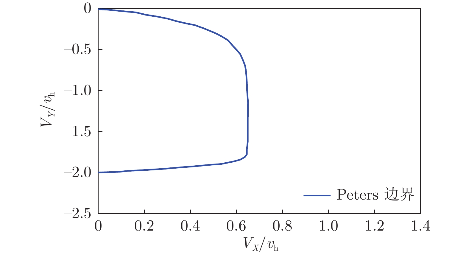
图 11 CD~α计算与试验结果对比(脉冲燃烧风洞和常规高超声速风洞)Fig. 11 CD~α comparison of numerical and experimental results from combustion heated impulse facility and hypersonic wind tunnel(1) 脉冲燃烧风洞等温壁计算得到的阻力系数比常规高超声速风洞大7%(迎角6°)~17%(迎角-2°),迎角越小,差异越大。这个差异由多方面因素导致,主要有雷诺数、比热比、壁温比等。
(2) 针对同一个模型,分别采用脉冲燃烧风洞和常规高超声速风洞的模拟参数计算(壁面都取绝热壁条件),此时得到的结果差异应该排除了壁温比的影响,而反映了两个风洞模拟条件(如雷诺数、比热比)不同引起的变化量,计算获得的这一部分的影响量约为3%(迎角6°)~6%(迎角-2°)。
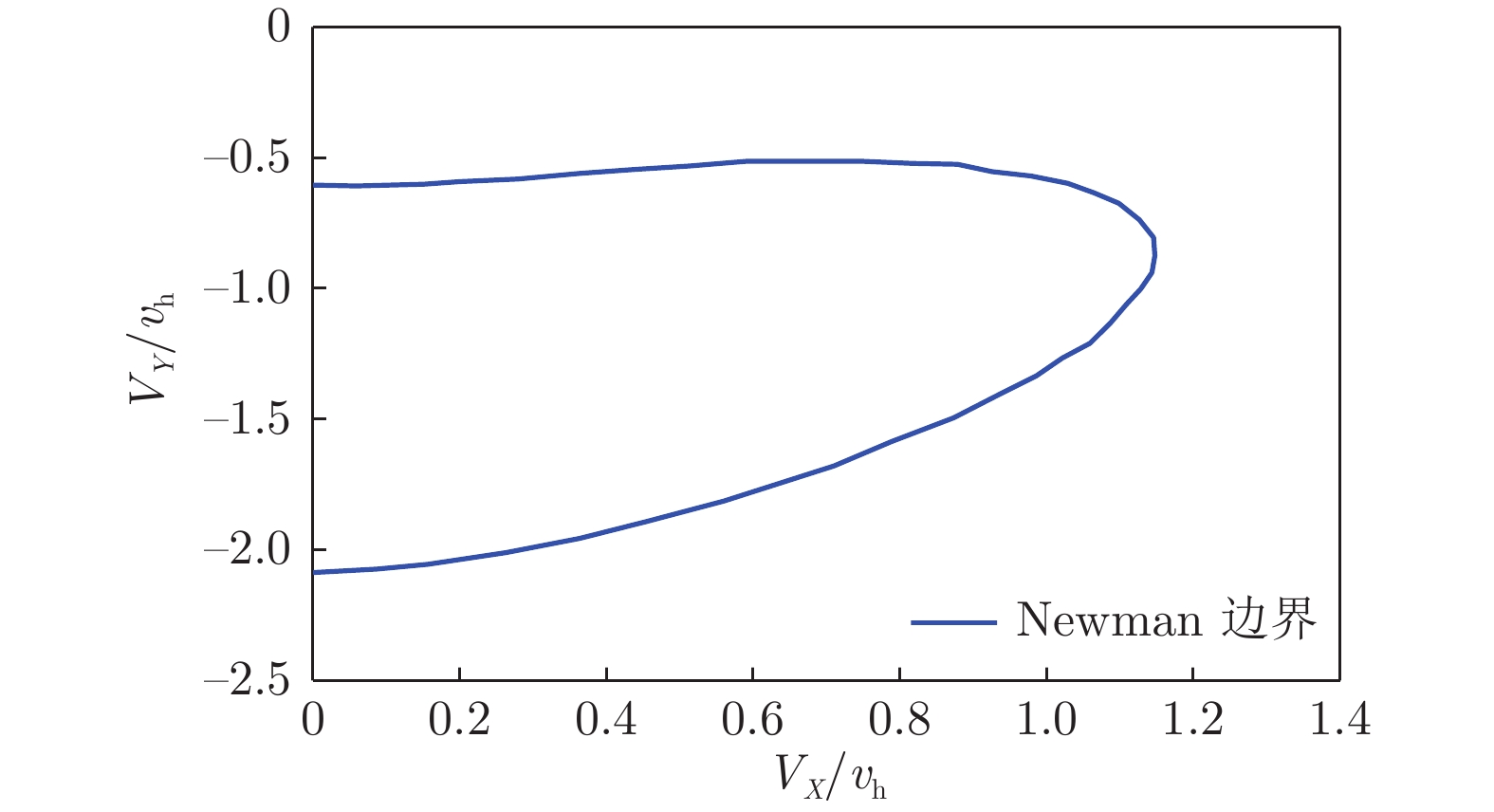
(3) 除去两个风洞模拟条件(如雷诺数、比热比)不同引起的阻力变化量,可得到壁温比的影响量约为4%(迎角6°)~12%(迎角-2°),迎角越小,差异越大。
5 结论
通过脉冲燃烧风洞与常规高超声速风洞不通气高超标模对比试验和计算,得到如下结论:
(1) 脉冲燃烧风洞获得的气动力系数变化规律与常规高超声速风洞一致;
(2) 雷诺数、壁温比对阻力系数均有影响,其中壁温比影响显著,脉冲燃烧风洞获得的阻力系数明显大于常规高超声速风洞;
(3) 水凝结对不通气高超标模的轴向力影响较小,对法向力影响较大,且不同迎角状态影响量不同。
-
![]()
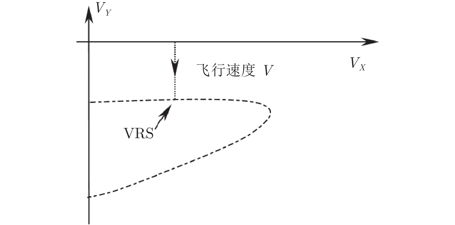
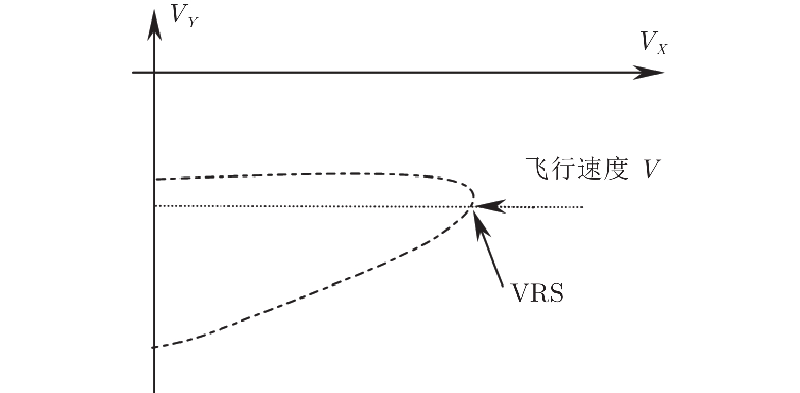
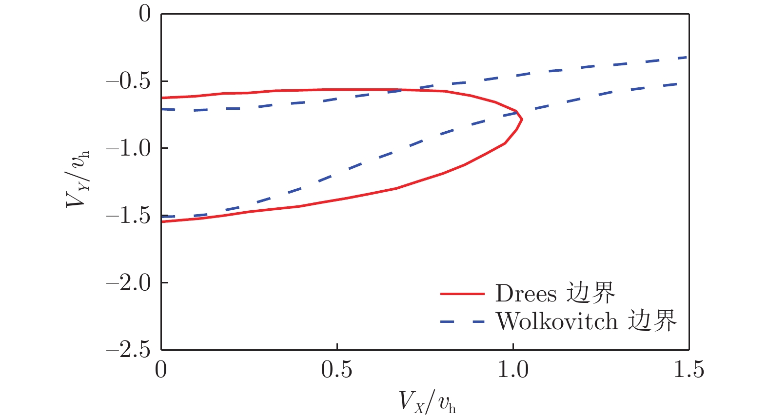
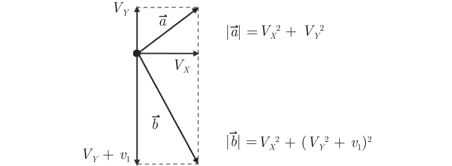
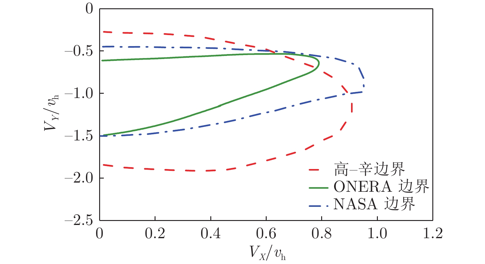
图 1 3种涡环状态边界对比
Fig. 1 Comparison of three kinds of vortex ring state boundaries commonly used in Engineering
![]()
![]()
![]()
![]()
![]()
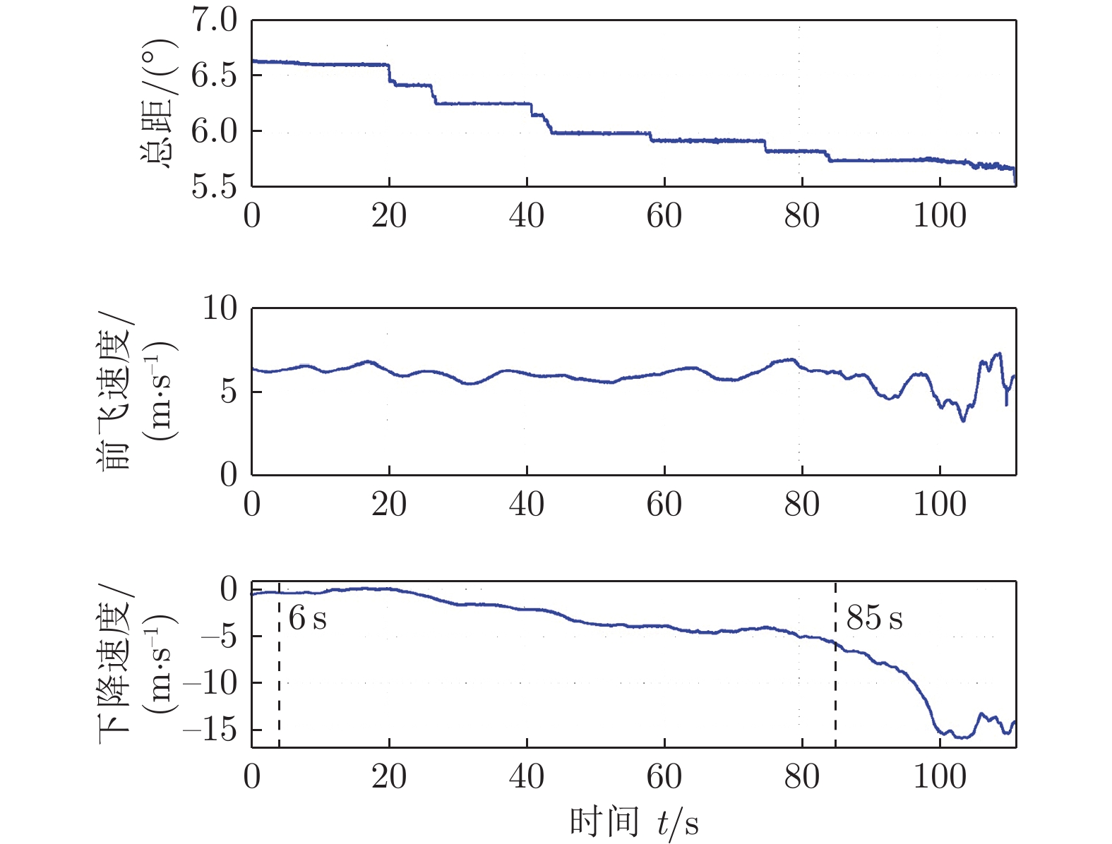
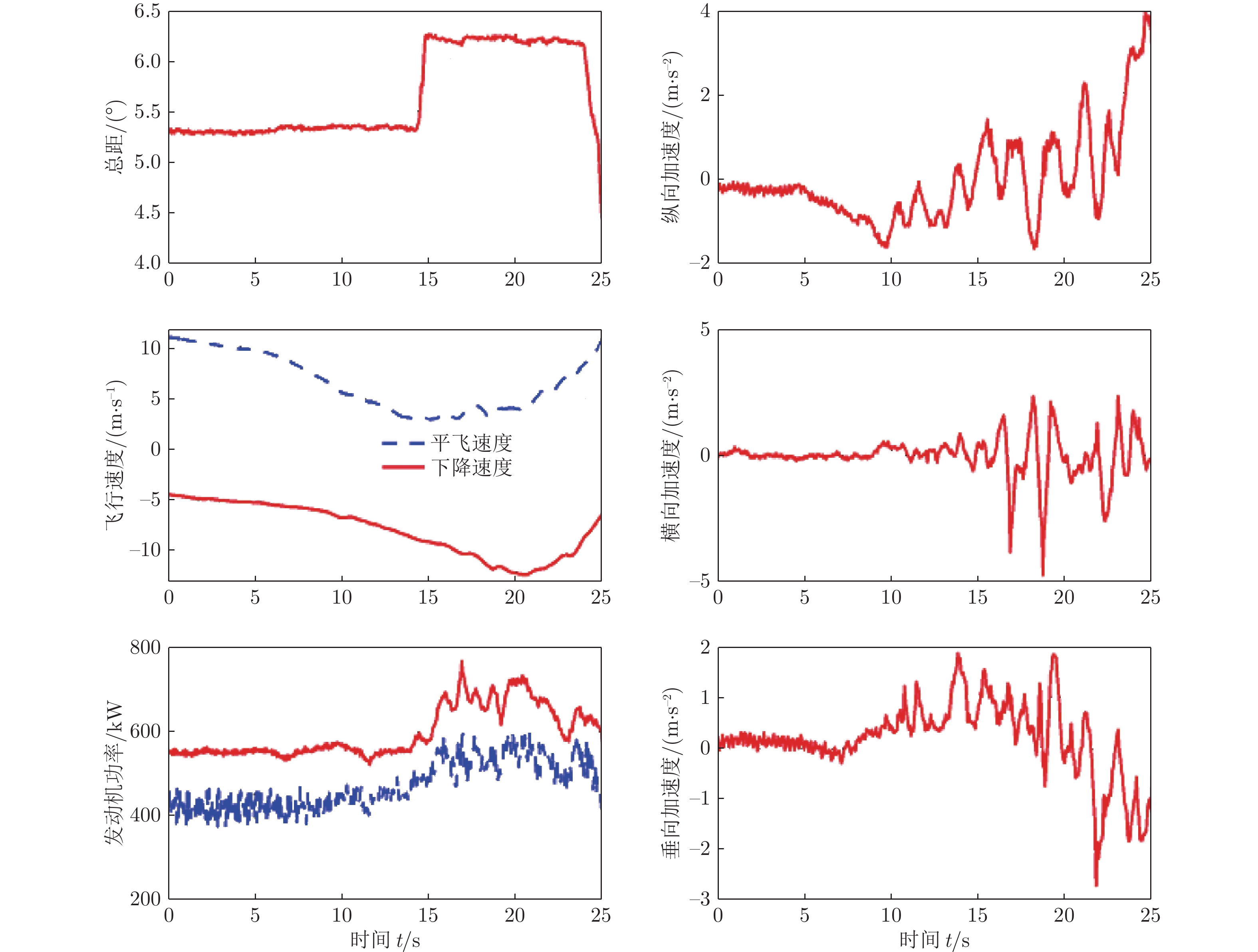
图 6 涡环状态下直升机对总距提升的响应[18]
Fig. 6 Response of helicopter to collective pitch increase in vortex ring state
![]()
![]()
![]()
![]()
![]()
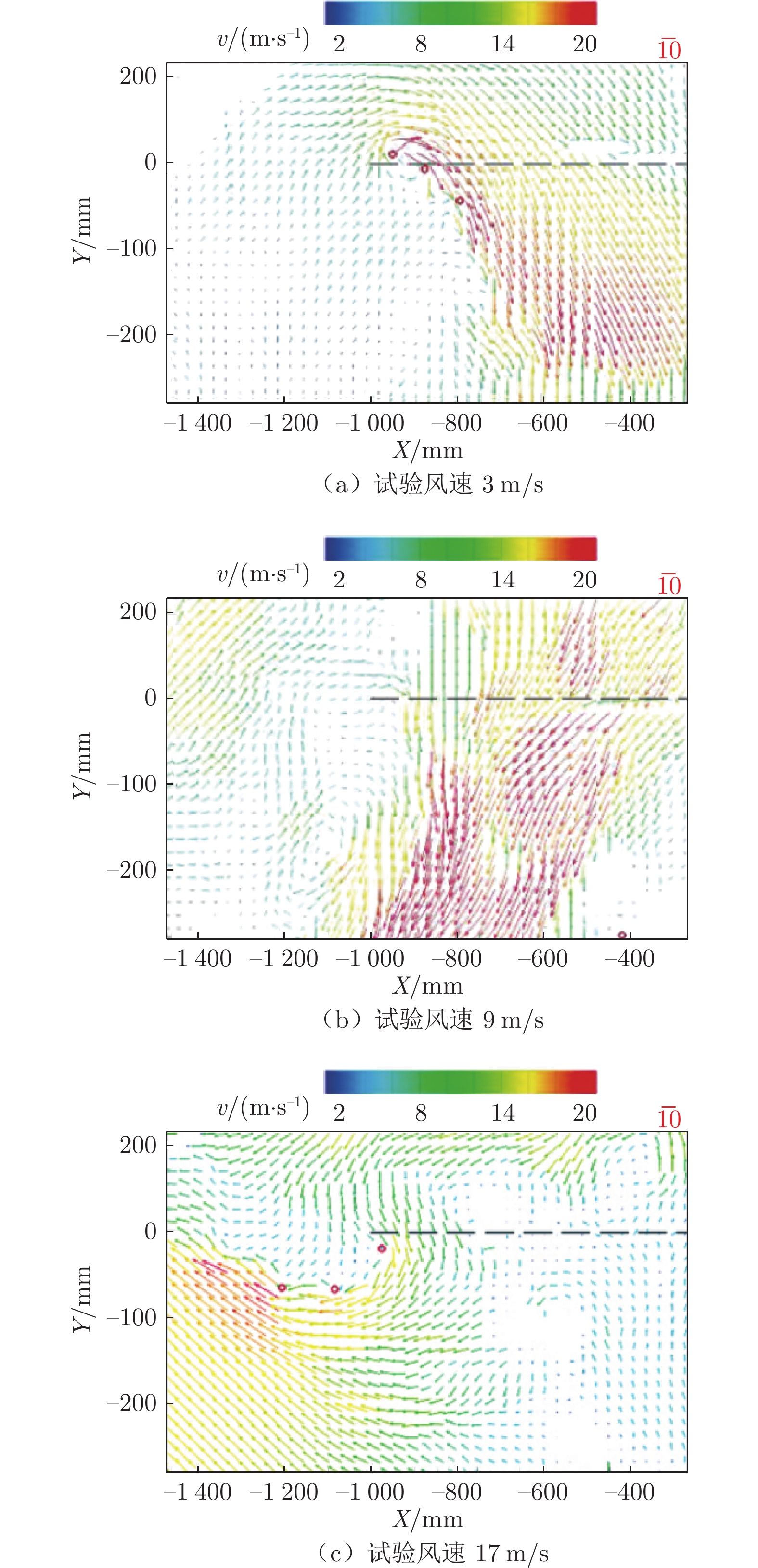
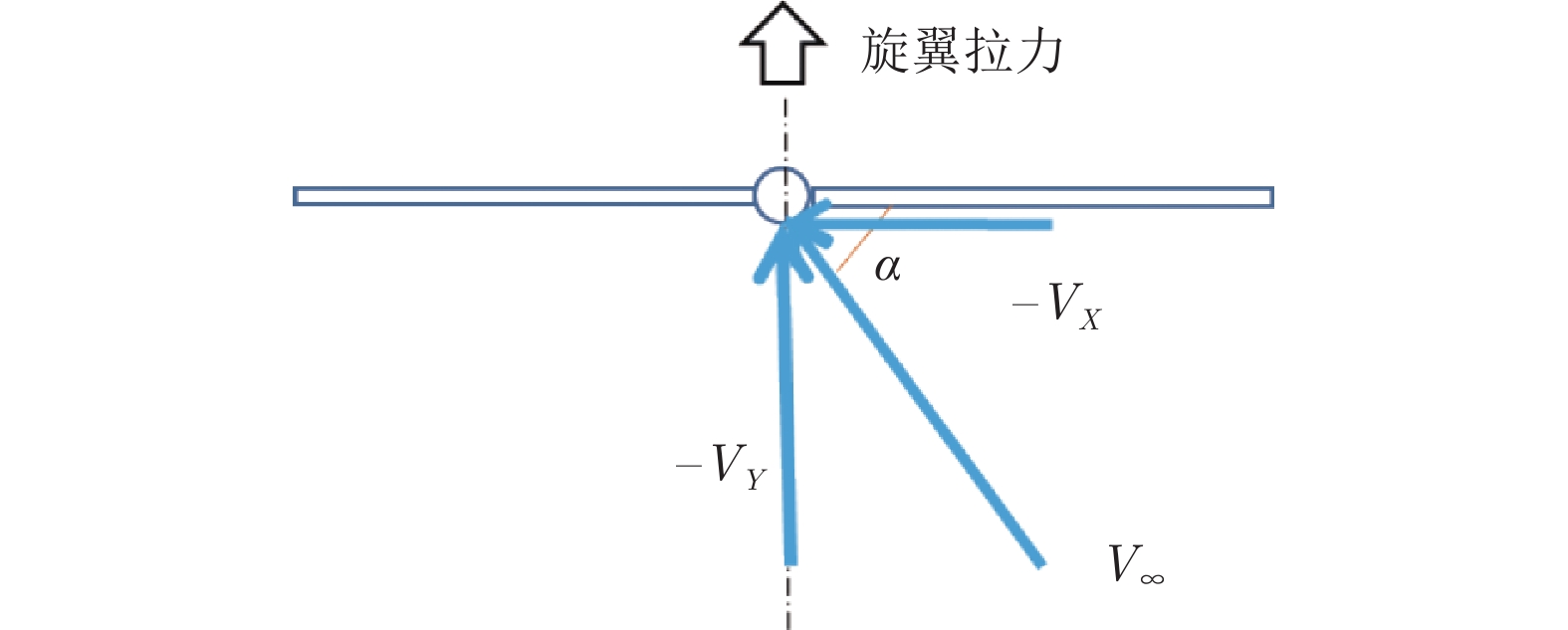
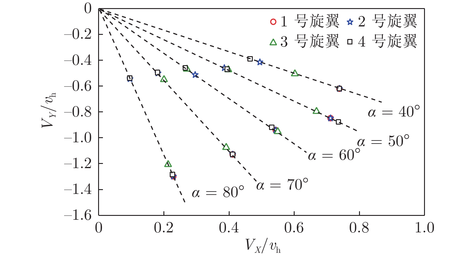
图 21 试验风速与下滑角示意图
Fig. 21 Schematic diagram of glide angle between test wind speed and rotor
![]()
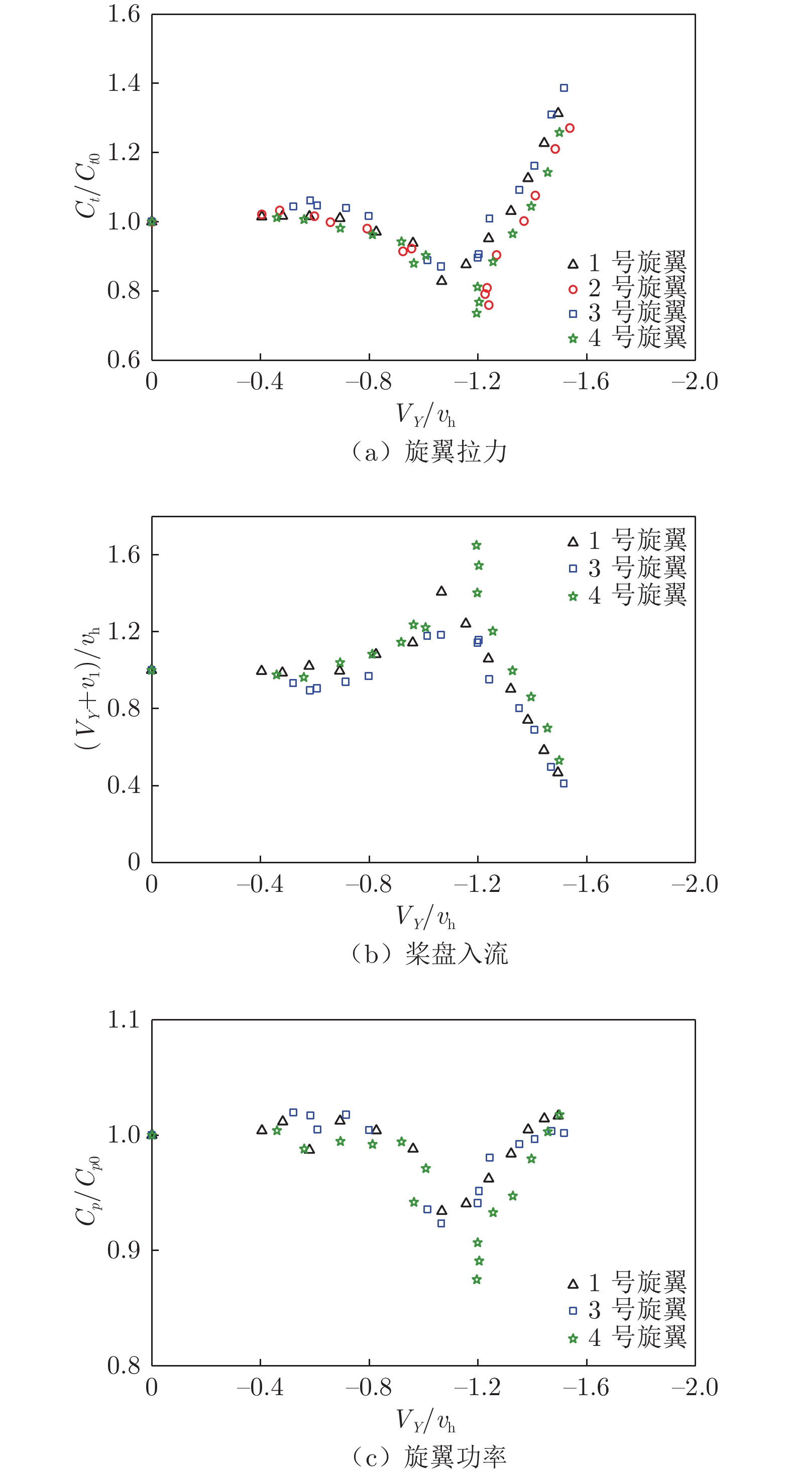
图 22 旋翼在垂直下降状态的气动特性
Fig. 22 Aerodynamic characteristics of each rotor in vertical descent
![]()
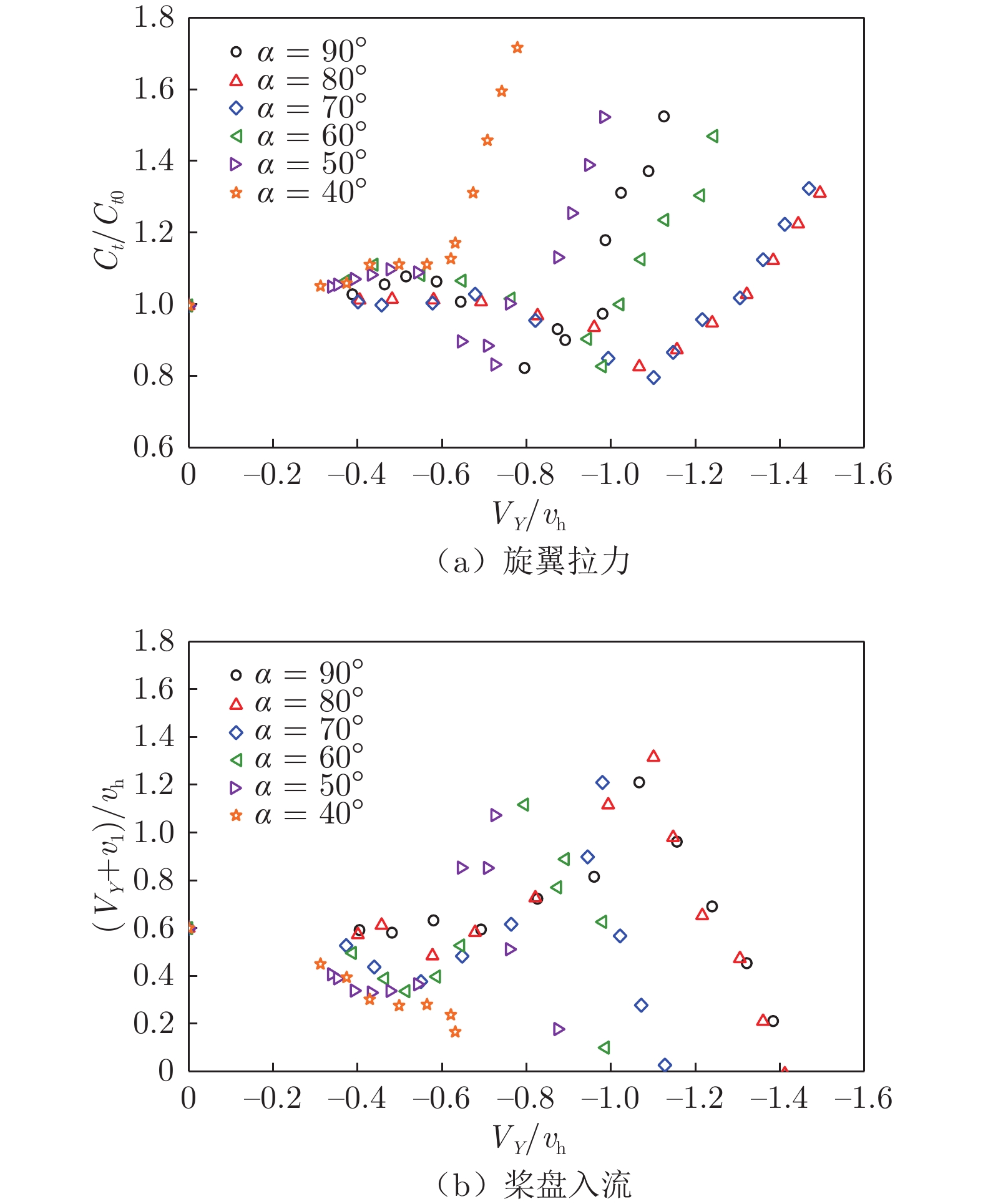
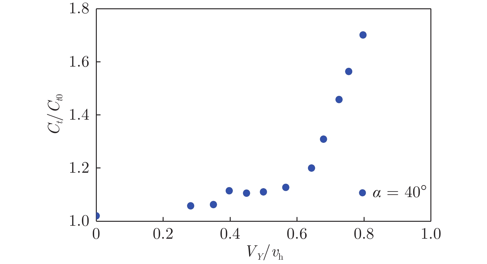
图 23 1号旋翼在不同下滑角下的气动特性
Fig. 23 Aerodynamic characteristics of No. 1 rotor at different glide angles
![]()
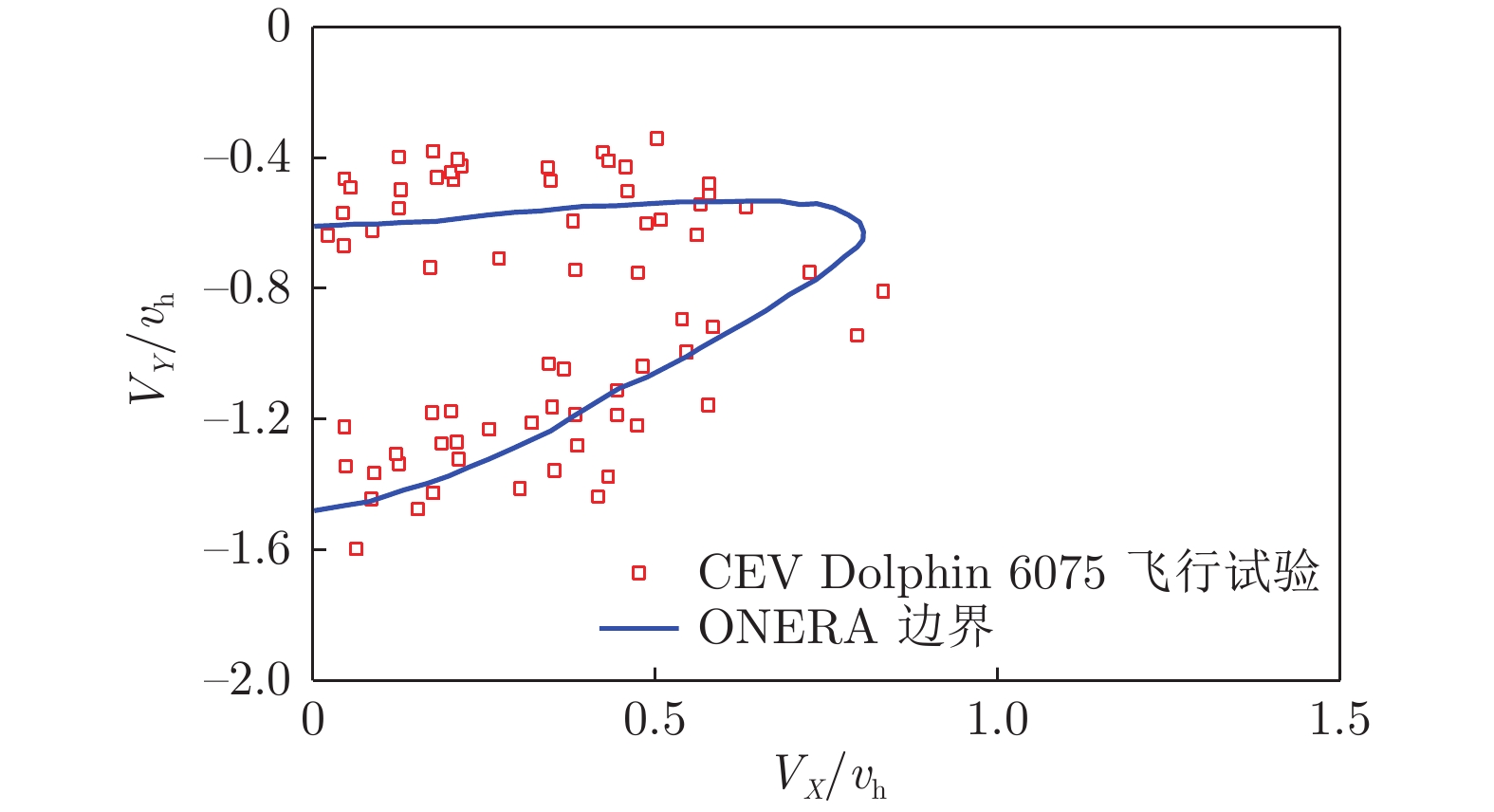
图 25 从风洞试验数据提取的涡环状态边界
Fig. 25 Vortex ring state boundary extracted from wind tunnel test data
![]()
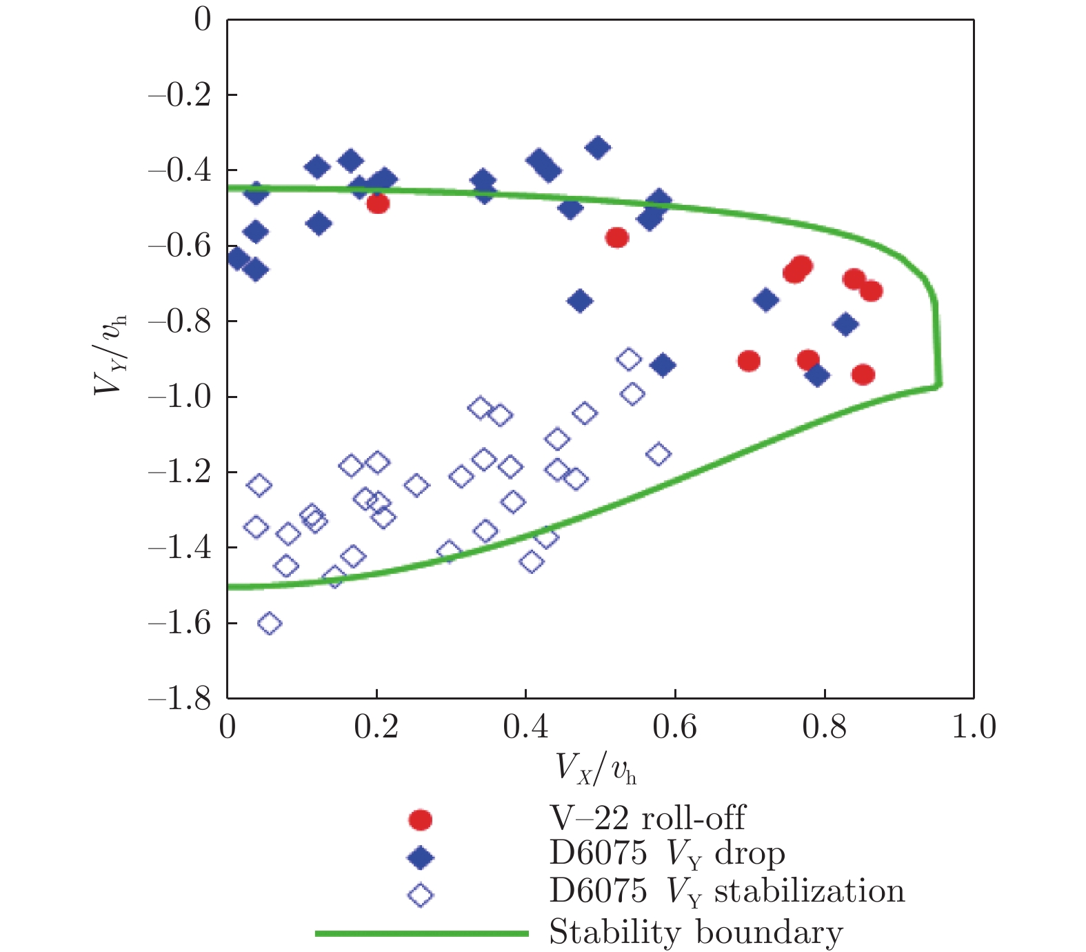
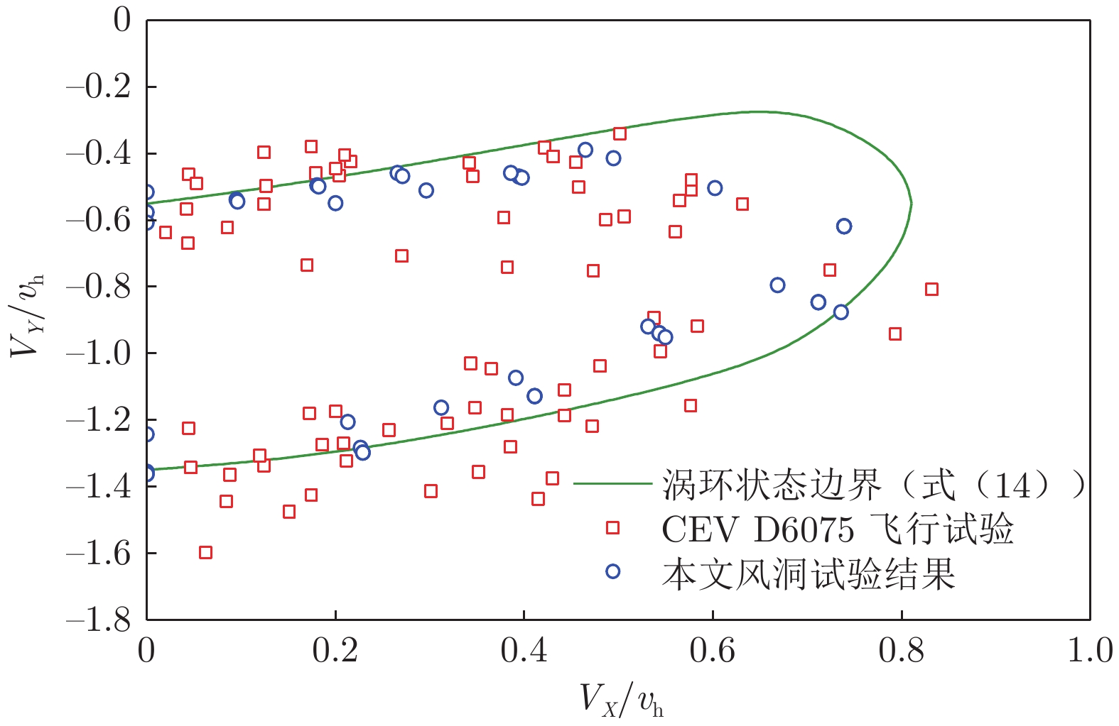
图 26 式(14)计算的涡环状态边界与风洞试验和CEV飞行试验结果对比
Fig. 26 Comparison of vortex ring state boundary calculated by equation 14 with wind tunnel test results and CEV flight test results
表 1 国内外已开展的涡环状态旋翼性能测量试验
Table 1 Tests of rotor performance in vortex ring state
研究者 时间 参考
文献桨叶
片数旋翼半径
/mm旋翼转速
/(r﹒min−1)扭转角/(°) 下降姿态 试验环境 Castles、Gray 1951 [45] 3 610、914 1200、1600 0、−12 垂直下降 直径2.74 m风洞 Mort、Yaggy 1963 [46] 3 1448、1829 700~1410、
700~1100−22.4、
−46.6斜下降、垂直下降 NFAC Washizu、Azuma、Koo等 1966 [47] 3 549 1000 −8.33 斜下降、垂直下降 滑轨 Azuma、Obata 1968 [44] 3 550 1000 −8,0 垂直下降 直径3 m风洞 Empey、Ormiston 1974 [48] 2 162 13250 0 斜下降、垂直下降 2.13 m × 3 m风洞 辛宏、高正 1993-1996 [14-16] 2 549 1406 0、 −5.5、−9.22 斜下降、垂直下降 悬臂机 Betzina 2001 [49] 3 610 1800 −41 斜下降、垂直下降 NFAC  下载: 导出CSV
表 2 旋翼模型参数
Table 2 Parameters of rotor models
编号 半径/mm 弦长/mm 扭转角/(°) 桨尖形状 翼型厚度 转速/(r﹒min−1) 1 550 135 0 抛物线后掠 12% 3000 2 550 135 −8 抛物线后掠 11.3% 3000 3 550 135 −8 抛物线后掠 12% 2600 4 450 97 −6.7 矩形 14% 3700
下载: 导出CSV
-
[1] 陆洋, 高正. 直升机涡环状态边界与飞行安全[J]. 航空科学技术, 2008, 15(5): 14–17. DOI: 10.3969/j.issn.1007-5453.2008.05.004 LU Y, GAO Z. Helicopter Vortex-Ring state boundary and flight safety[J]. Aeronautical Science and Technology, 2008, 15(5): 14–17. doi: 10.3969/j.issn.1007-5453.2008.05.004
[2] 赵秀云. 直升机垂直下降的涡环边界分析[C]//98珠海航空学术会议第14届全国直升机年会论文集. 1998. [3] KISOR R, BLYTH R, BRAND A, et al. V-22 low speed/high rate of descent test summary[C]//American Helicopter Society Annual. 2004.
[4] NORIHIRO G, SHINSUKE E, TOSHIYUKI I, et al. Aircraft accident investigation report[R]. Japan Transport Safety Board, 2013.
[5] HELLNER C, KJELLBERG U, HELLSTRÖM C R. Accident involving helicopter type 11 no 334 (Agusta Bell 412HP) over Bottensjön, Karlsborg, O county, Sweden, on 25 March 2003 [R]. Report RM 2005: 01e, 2005.
[6] Report on the accident to AS332 L2 Super Puma helicopter, G-WNSB on approach to Sumburgh Airport on 23 August 2013[R/OL]. Aircraft Accident Report No: 1/2016. (2016-03-15)[2022-06-27]. https://assets.publishing.service.gov.uk/media/56f169aa40f0b6038500001e/Eurocopter_AS332_L2_Super_Puma_G-WNSB_04-16.pdf
[7] Aerossurance. French cougar crashed after entering VRS when coming into hover[EB/OL]. (2021-10-3)[2022-10-28]. https://aerossurance.com/helicopters/alat-cougar-fatal-hover-vrs.
[8] КОМИТЕТ М А. Окончательный отчет вертолет Ми-8Т[R]. RA-24255, 2014.
[9] КОМИТЕТ М А. По результатам расследования авиационного происшествия[R]. RA-06029, 2018.
[10] 王畅, 程蒙, 马帅. 直升机尾桨失效事故案例分析[J]. 重庆交通大学学报(自然科学版), 2022, 41(4): 126–132. DOI: 10.3969/j.issn.1674-0696.2022.04.19 WANG C, CHENG M, MA S. Case study on accident caused by loss of tail-rotor effectiveness[J]. Journal of Chongqing Jiaotong University(Nature Science), 2022, 41(4): 126–132. doi: 10.3969/j.issn.1674-0696.2022.04.19
[11] 费景荣. 某型直升机异常离地状态的尾桨涡环特性分析[J]. 空军工程大学学报, 2022, 23(1): 79–82. DOI: 10.3969/j.issn.1009-3516.2022.01.011 FEI J R. An analysis of characteristics of tail rotor vortex ring in an abnormal lift off state for a certain type of helicopter[J]. Journal of Air Force Engineering University, 2022, 23(1): 79–82. doi: 10.3969/j.issn.1009-3516.2022.01.011
[12] AIRBUS. The H160 opened a new chapter in the history of Airbus helicopters. Joining its rotorcraft product range in a size that is positioned between the company’s H145 and H175, this innovative medium helicopter became the first member of the H generation[EB/OL]. [2022-10-28]. https://www.airbus.com/en/products-services/helicopters/civil-helicopters/h160.
[13] BASSET P M, CHEN C, PRASAD J V R, et al. Prediction of vortex ring state boundary of a helicopter in descending flight by simulation[J]. Journal of the American Helicopter Society, 2008, 53(2): 139–151. doi: 10.4050/JAHS.53.139
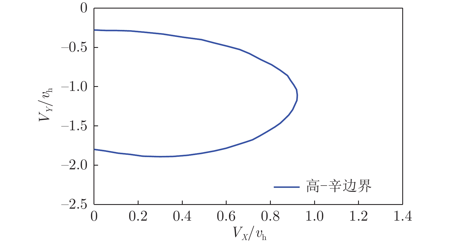
[14] 辛宏, 高正. 直升机涡环区域边界包线的确定[J]. 气动实验与测量控制, 1996, 10(1): 14–19. [15] XIN H, GAO Z. An experimental investigation of model rotors operating in vertical descent[C]//Proc of 19th European Rotorcraft Forum. 1993.
[16] XIN H, GAO Z. A prediction of the vortex-ring state boundary based on model tests[J]. Transactions of Nanjing University of Aeronautics and Astronautics, 1994, 11(2): 159–164.
[17] JIMENEZ J, DESOPPER A, TAGHIZAD A, et al. Induced velocity model in steep descent and vortex-ring state prediction[C]//8th European Rotorcraft Forum Proceedings. 2002.
[18] TAGHIZAD A, JIMENEZ J, BINET L, et al. Experimental and theoretical investigations to develop a model of rotor aerodynamics adapted to steep descents[C]//Proc of Presented at the American Helicopter Society 58th Annual Forum. 2002.
[19] JOHNSON W. Model for vortex ring state influence on rotorcraft flight dynamics[C]// Proc of AHS 4th Decennial Specialists' Conference on Aeromechanics. 2004.
[20] JOHNSON W. Rotorcraft aeromechanics[M]. Cambridge: Cambridge University Press, 2013.
[21] 孙文胜, 胡凯亮, 张泰峰, 等. 直升机舰载飞行涡环边界的确定[J]. 科技创新导报, 2010, 7(7): 107. doi: 10.3969/j.issn.1674-098X.2010.07.090 [22] 胡奉言, 陈铭, 邹思汉, 等. 直升机尾桨涡环状态边界研究[C]//湖南省力学学会2015学术年会论文集. 2015. [23] 马鸿儒, 穆志韬, 李洪伟, 等. 基于桨盘倾角的直升机涡环状态边界修正计算方法[J]. 空气动力学学报, 2018, 36(1): 31–34. DOI: 10.7638/kqdlxxb-2015.0203 MA H R, MU Z T, LI H W, et al. Revised calculation method for helicopter vortex-ring state boundary based on flight attitude[J]. Acta Aerodynamica Sinica, 2018, 36(1): 31–34. doi: 10.7638/kqdlxxb-2015.0203
[24] VARNES D J. Development of a helicopter vortex ring statewarning system through a moving map display computer[D]. Monterey: Naval Postgraduate School, 1999.
[25] KISOR R L. Control system for rotorcraft for preventing the vortex ring state: US6880782[P]. 2005-04-19.
[26] ABILDGAARD M, BINET L. Active sidesticks used for VRS avoidance[C]// Proc of European Rotorcraft Forum (ERF). 2009.
[27] BINET L, ABILDGAARD M, TAGHIZAD A, et al. VRS avoidance as active function on side-sticks[C]// Proc of American Helicopter Society 65th annual forum. 2009.
[28] DANG-VU B. Vortex ring state protection flight control law[C]// Proc of 39th European Rotorcraft Forum. 2013.
[29] KISOR R L. Method and apparatus for preventing adverse effects of vortex ring state: EP1620311 [P]. 2013-12-18.
[30] 陈坚强. 基于神经网络的直升机涡环告警方法研究[D]. 南京: 南京航空航天大学, 2018. CHEN J Q. Research on helicopter vortex ring warning method based on neural network[D]. Nanjing: University of Aeronautics and Astronautics, 2018.
[31] 李高华. 直升机旋翼涡环状态流场高分辨率数值模拟方法研究[D]. 上海: 上海交通大学, 2018. LI G H. Study of high resolution numerical method for helicopter rotor in vortex ring state[D]. Shanghai: Shanghai Jiao Tong University, 2018.
[32] STRYCZNIEWICZ W, SURMACZ K. Badania eksperymentalne stanu pierścienia wirowego na wirniku nośnym śmigłowca metodą anemometrii obrazowej (PIV)[J]. Transactions of the Institute of Aviation, 2014, 235(2): 17–27. doi: 10.5604/05096669.1130234
[33] Surmacz K, Ruchała P, Stryczniewicz W. Wind tunnel tests of the development and demise of Vortex Ring State of the rotor[C]//Advances in Mechanics: Theoretical, Computational and Interdisciplinary Issues, Proceedings of the 3rd Polish Congress of Mechanics (PCM) and 21st International Conference on Computer Methods in Mechanics (CMM). 2015: 8-11.
[34] 陆洋, 高正, 黄文明, 等. 直升机涡环状态边界的飞行试验研究[J]. 南京航空航天大学学报, 2001, 33(5): 405–409. DOI: 10.3969/j.issn.1005-2615.2001.05.001 LU Y, GAO Z, HUANG W M, et al. Flight test investigation of helicopter Vortex-Ring state boundary[J]. Journal of Nanjing University of Aeronautics & Astronautics, 2001, 33(5): 405–409. doi: 10.3969/j.issn.1005-2615.2001.05.001
[35] BRAND A, DREIER M, KISOR R, et al. The nature of vortex ring state[J]. Journal of the American Helicopter Society, 2011, 56(2): 22001. doi: 10.4050/JAHS.56.022001
[36] DE BOTHEZAT G. The general theory of blade screws including propellers, fans, helicopter screws, helicoidal pumps, turbo-motors, and different kinds of helicoidal blades[R]. NACA-TR-29, 2013.
[37] HUNT H H. Aerodynamics for Naval Aviators: NAVWEPS 00-80T-80[M]. Ravenio Books, 2016.
[38] SHEVELL, R S. Fundamentals of Flight [M]. New Jersey: Prentice Hall, Inc. , 1988.
[39] ADMINISTRATION F A. Rotorcraft flying handbook[M]. New York: Skyhorse Publishing Inc. , 2007.
[40] Transport Canada. helicopter flight training manual. Second Edition) [M]. Transport Canada, 2006.
[41] Federal Aviation Administration. Helicopter Flying Handbook: FAA-H-8083-21B[M]. Independently published, 2022.
[42] REEDER J P, GUSTAFSON F B. On the flying qualities of helicopters[R]. NACA-TN-1799, 1949.
[43] STEWART W. Helicopter behaviour in the vortex-ring conditions[R]. R. &M. No. 3117, 1959.
[44] AZUMA A, OBATA A. Induced flow variation of the helicopter rotor operating in the vortex ring state[J]. Journal of Aircraft, 1968, 5(4): 381–386. doi: 10.2514/3.43954
[45] CASTLES W Jr, GRAY R B. Empirical relation between induced velocity, thrust, and rate of descent of a helicopter rotor as determined by wind-tunnel tests on four model rotors[R]. NACA-TN-2474, 1951.
[46] MORT K W, YAGGY P F. Wind-tunnel tests of two vtol propellers in descent[R]. NASA-TN-D-1766, 1963.
[47] WASHIZU K, AZUMA A, KOO J, et al. Experiments on a model helicopter rotor operating in the vortex ringstate[J]. Journal of Aircraftdoi, 1966, 3(3): 225–230. doi: 10.2514/3.43729
[48] EMPEY R W, ORMISTON R A, USAAMRDL, et al. Tail rotor thrust on a 5.5 Ft. helicopter model in ground effect[C]// Proc of Presented at the 30th Annual National Forum. 1974.
[49] BETZINA M D. Tiltrotor descent aerodynamics: a small-scale experimental investigation of vortex ring state[C]// Proc of American Helicopter Society 57th Annual Forum. 2001.
[50] STALEWSKI W, SURMACZ K. Investigations of the vortex ring state on a helicopter main rotor based on computational methodology using URANS solver[C]// Proc of 9th EASN International Conference on “Innovation in Aviation & Space”. 2019. doi: 10.1051/matecconf/201930402011.
[51] PADFIELD G D. Helicopter flight dynamics: including a treatment of tiltrotor aircraft[J]. The Aeronautical Journal, 2018, 123(1266): 1333–1334. doi: 10.1017/aer.2019.103
[52] 黄明其, 王亮权, 何龙, 等. 旋翼涡环状态气动特性和参数变化的风洞试验[J]. 航空动力学报, 2019, 34(11): 2305–2315. DOI: 10.13224/j.cnki.jasp.2019.11.001 HUANG M Q, WANG L Q, HE L, et al. Wind tunnel test of aerodynamic characteristics and parametric variation for rotor in vortex ring state[J]. Journal of Aerospace Power, 2019, 34(11): 2305–2315. doi: 10.13224/j.cnki.jasp.2019.11.001
[53] LEISHMAN J G, BHAGWAT M J, ANANTHAN S. Free-vortex wake predictions of the vortex ring state for single-rotor and multi-rotor configurations[C]//AHS International, 58th Annual Forum Proceedings. 2002.
[54] BROWN R E, NEWMAN S J, PERRY F J. Blade twist effects on rotor behaviour in the vortex ring state[C]// Proc of 28th European Rotorcraft Forum. 2002.
[55] WOLKOVITCH J. Analytical prediction of vortex-ring boundaries for helicopters in steep descents[J]. Journal of the American Helicopter Society, 1972, 17(3): 13–19. doi: 10.4050/JAHS.17.13
[56] DREES J M. A theory of airflow through rotors and its application to some helicopter problems[J]. Journal of the Helicopter Association of Great Britain, 1949, 3(2): 79–104.
[57] DREES J M, LUCASSEN L R, HENDAL W P. Airflow through helicopter rotors in vertical flight[M]. Netherlands: Nationaal Lucht-en Ruimtevaartlaboratorium, 1949.
[58] DREES J M. The field of flow through a helicopter rotor obtained from wind tunnel smoke tests[J]. Aircraft Engineering, 1951, 23(266): 107–111.
[59] PETERS D A, CHEN S Y. Momentum theory, dynamic inflow, and the vortex-ring state[J]. Journal of the American Helicopter Society, 1982, 27(3): 18–24. doi: 10.4050/JAHS.27.18
[60] GESSOW A, MYERS G C. Aerodynamics of the Helicopter[M]. New York: Frederick Ungar, 1967.
[61] NEWMAN S, RICHARD B, JOHN P, et al. Predicting the onset of wake breakdown for rotors in descending flight[J]. Journal of the American Helicopter Societydoi, 2003, 48(1): 28-38. doi: 10.4050/JAHS.48.28.


计量
- 文章访问数: 340
- HTML全文浏览量: 200
- PDF下载量: 83