Measurement of 3D airblast swirl atomization field at low temperature with off-axis holography
-
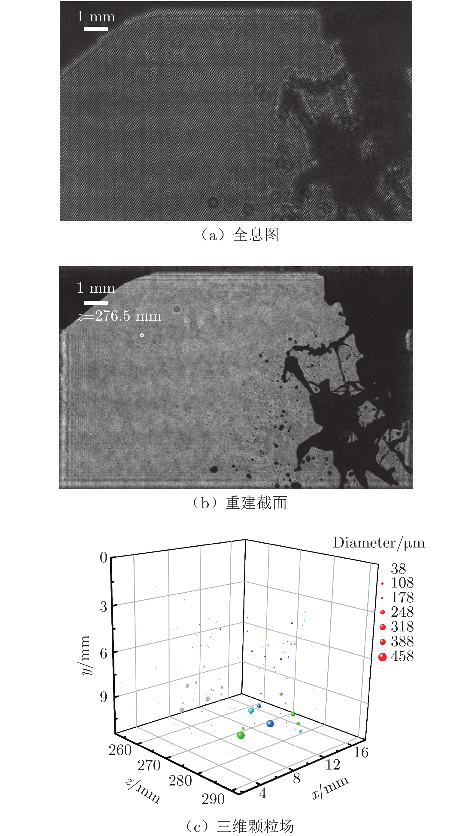
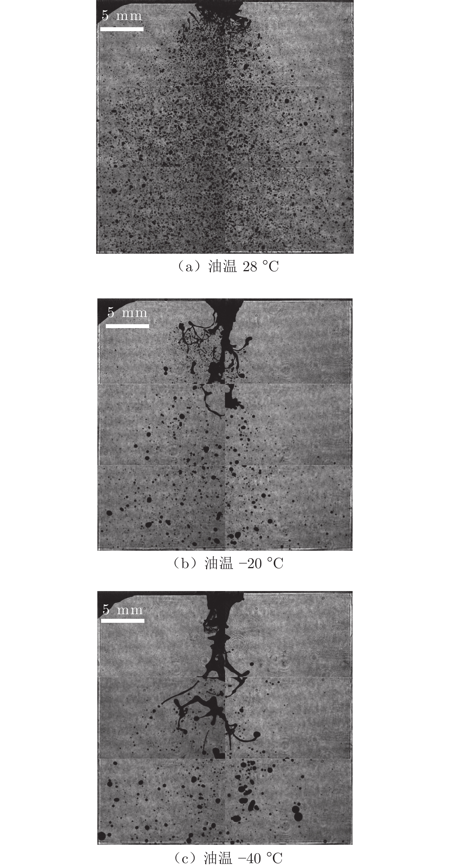
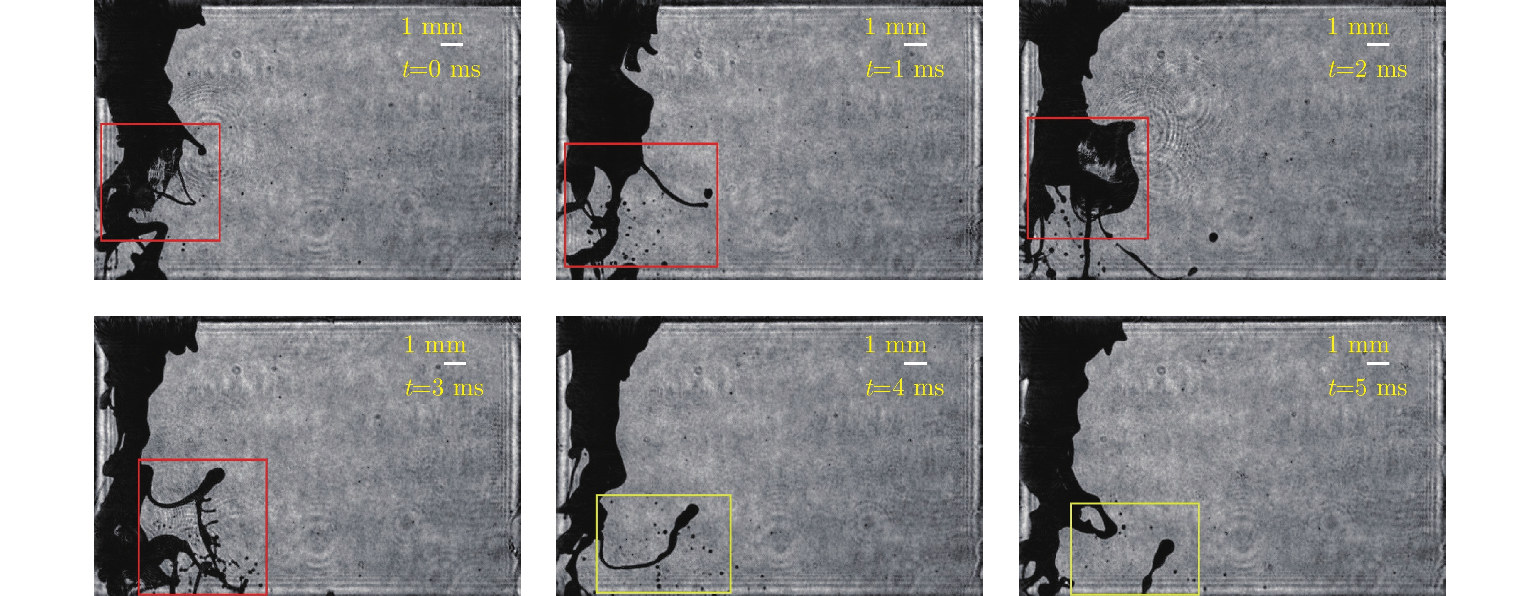
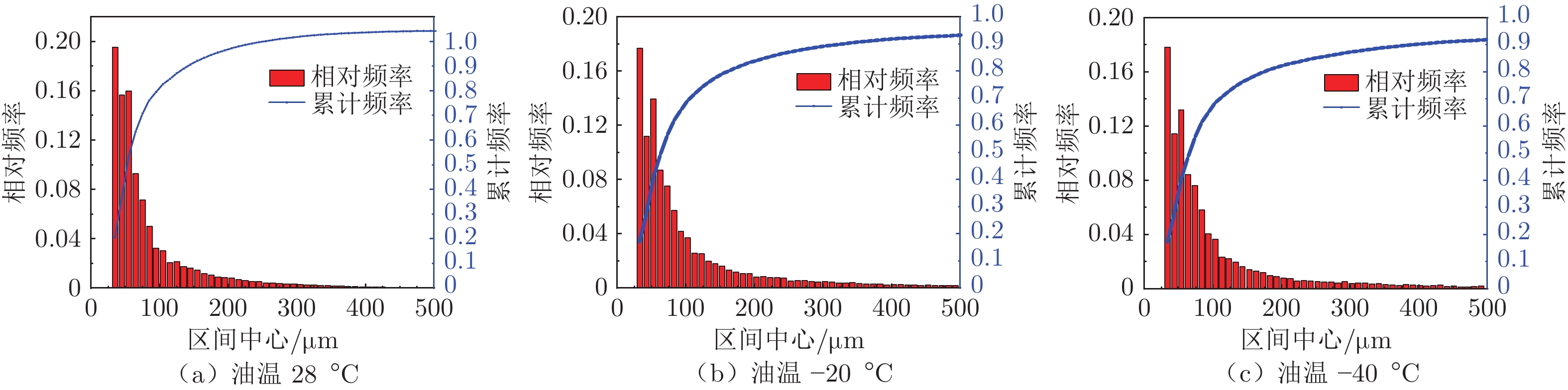
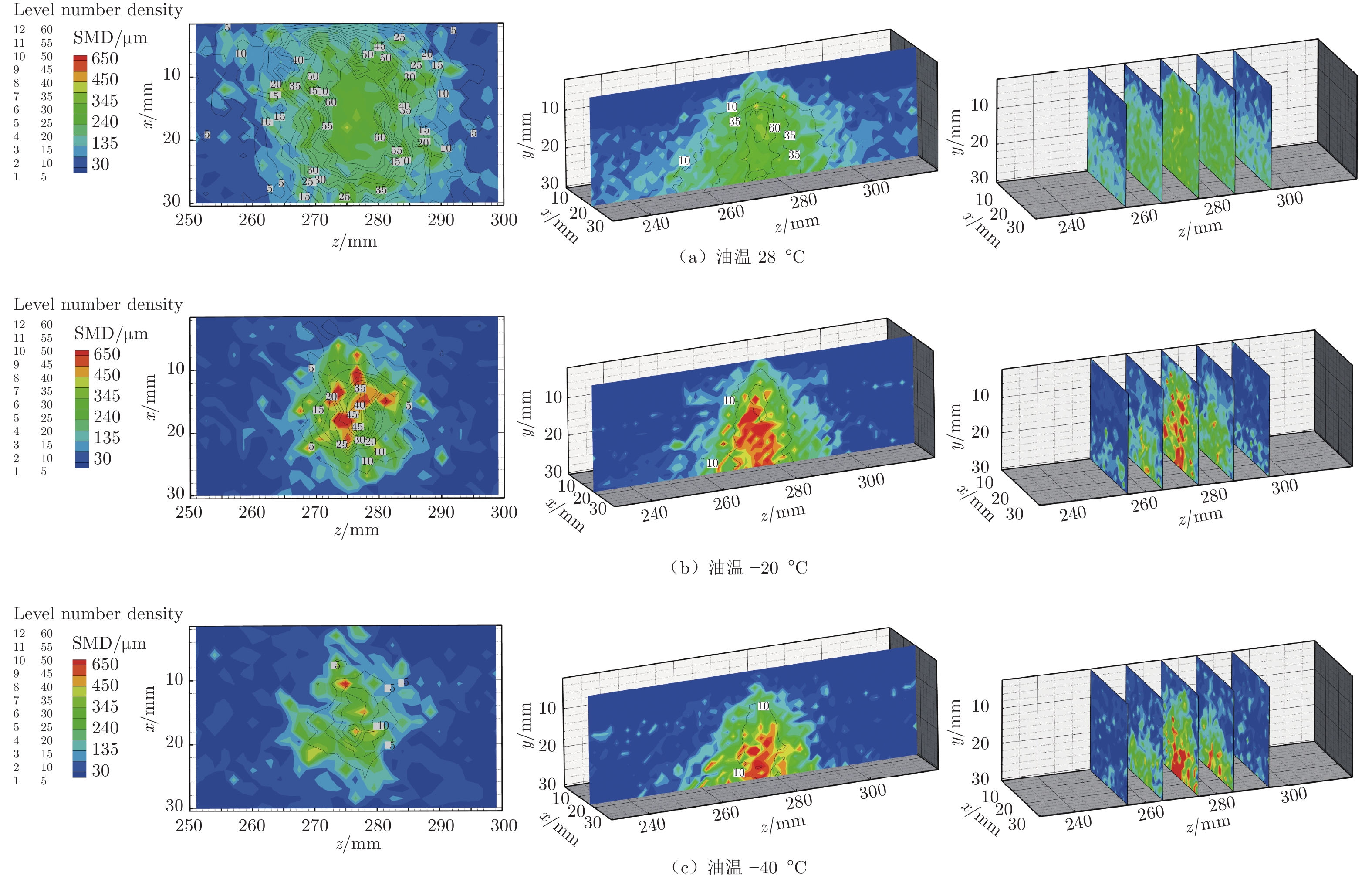
摘要: 为研究低油温工况下气动旋流雾化喷嘴近场雾化特性,建立了25 kHz皮秒脉冲激光离轴全息系统,对1 kPa气压、0.03 MPa油压和–40~28 ℃油温工况下喷嘴下游30 mm内近场雾化过程进行了三维可视化测试。实验获取了包含非球形液滴的近喷嘴雾化场清晰图像,记录了液膜袋状破碎与液丝分解等典型雾化动态过程。通过颗粒识别与定位,获取了雾化场中尺寸30~1500 μm的液滴粒径及三维位置,统计得到雾化场索特平均直径(SMD)的三维分布信息。研究发现:在气压1 kPa、油压0.03 MPa工况下,液滴粒径主要分布在200 μm以内,其中30~40 μm粒径占比最高,均在15%以上;三维粒径分布表现为雾锥中央粒径较大,边缘区域粒径较小;油温降低对雾化效果恶化显著,使雾锥体积缩小、雾化液滴密度降低且均匀性下降;油温从28 ℃降至–20 ℃时,下游截面中心粒径从300 μm左右增大至450 μm以上,局部大于650 μm;–40 ℃时,喷嘴下游出现大型液柱与多枝状液膜、液丝结构,燃油分解破碎距离进一步延长。实验结果证实了高速离轴全息技术在低油温工况下喷嘴近场雾化特性三维可视化诊断中的可行性,获取的雾化场三维参数可为喷嘴结构设计优化及雾化模型研究提供数据参考。Abstract: A 25 kHz picosecond pulsed digital off-axis holography system is applied to measure the near-nozzle atomization characteristics of an airblast swirl atomizer under low oil temperature conditions. Experiments are carried out for the near-nozzle atomization process 30 mm down-stream from the nozzle exit under air pressure of 1 kPa and oil pressure of 0.03 MPa. The oil temperature varies from –40 ℃ to 28 ℃. It is found that the atomization field in the near-nozzle region contains non-spherical droplets. Typical dynamic processes of atomization such as the breakup of films and filaments are visualized with clear images. The sizes and three-dimensional(3D) positions of droplets ranging from 30 to 1500 μm are obtained through particle identifica-tion and locating, thereafter statistics on 3D distribution of Sauter Mean Diameters(SMD) is obtained. It is found that under conditions of oil pressure of 0.03 MPa and air pressure of 1 kPa, the droplet diameter is mainly distributed within 200 μm, and droplets with size range 30–40 μm account for the largest proportion, above 15%. The 3D droplet size distribution is expressed as a cone where the central droplet size is larger than that on the edge; the decrease of oil temperature significantly deteriorates the atomization effect, which reduces the volume of the spray cone, and the density and the uniformity of atomized droplets; With oil temperature decreasing from 28 ℃ to –20 ℃, the central droplet diameter of the downstream cross-section increases from about 300 μm to over 450 μm and can be locally larger than 650 μm; with the oil temperature of –40 ℃, a large liquid core with multi-branched liquid films and filaments appears downstream of the nozzle, resulting in a longer breakup distance. The experimental results also demonstrate that the high-speed digital off-axis holography is a powerful tool for three-dimensional visualization and diagnostics of near-nozzle atomization under low oil temperatures conditions. This work can provide reference data for optimization of the nozzle structure design and the demonstration of the atomization model.
-
Keywords:
- digital off-axis holography /
- swirl atomization /
- droplet size /
- 3D /
- low temperature
-
0 引言
目前,要求地面试验设备完全模拟高超声速飞行环境是非常困难的,在一个试验设备上进行所有环境的模拟试验更是不可能的。因此,需要研制多种试验设备,以满足高超声速试验需求[1-5]。
常规高超声速风洞主要模拟参数是马赫数和雷诺数[6],其他一些参数则主要通过高焓试验设备来模拟[7-8]。
在高超声速风洞运行中,气源不仅要维持风洞所必须达到的压力比,还需要满足雷诺数模拟的要求。一般来说,风洞的总压要足够高。如果风洞连续工作,高的压力比和高总压将使风洞消耗很大的动力,因而高超声速风洞多为暂冲式。
暂冲式常规高超声速风洞的运行方式是:气罐中的压缩空气经过加热系统达到所需温度,然后通过型面喷管,在试验段形成所需的高超声速流场,最后经由超声速扩散段升压后进入引射排气系统,排入大气,或经过冷却器进入真空系统,由真空泵系统排入大气。常规高超声速风洞一般加热温度在800K以下,主要是为了防止气流冷凝,不能真实模拟实际总温(马赫数6时达到1800K),因此,开展发动机及飞行器一体化带动力试验还需要满足总温要求的高焓设备。
燃烧加热风洞是目前高超声速飞行器地面模拟试验尤其是带动力试验的主要设备。在过去的十几年间,中国空气动力研究与发展中心研制了不同尺度的脉冲燃烧风洞,探索了一体化飞行器设计、计算与试验技术[7-9]。在此基础上,发展了基于脉冲燃烧风洞的大尺度飞行器带动力一体化试验技术[10-11],提出了一种基于一体化试验直接测力结果的飞行器和发动机性能评估方法。
由于采用燃烧加热方式,无论是采用氢燃料还是碳氢燃料,都会产生水蒸气(H2O)、二氧化碳(CO2)等燃烧产物,即形成所谓“污染”。污染组分将造成风洞试验气体物理化学属性与真实空气存在一定差异,导致地面试验难以完全模拟真实飞行状态下的所有来流参数,且给地面试验结果向真实飞行状态的外推带来不确定性。为了尽可能降低这种不确定性,地面试验一般需要慎重考虑试验来流与模拟对象环境之间的参数匹配问题:即通过有选择地调整污染来流的某些状态参数,使之逼近对应的真实飞行环境,同时放弃一些无法兼顾的非关键参数,以尽可能达到飞行器气动与推进性能的可靠模拟。
目前主要有两种模拟方式:对于气动力试验,一般采用静温、静压、马赫数模拟;对于发动机性能试验,也可以采用总焓、动压、马赫数模拟。
中国科技大学杨基明、罗喜胜等[12-13]通过典型升力体飞行器的试验和计算研究,证明污染组分使得斜激波波后参数相对纯净空气有一定变化,从而造成模型表面压力及模型的气动力有一定变化,但变化量较小。相对于纯净空气来流,污染空气来流时发动机推力、单位推力、比冲均有所下降。脉冲燃烧风洞采用氢氧燃烧加热,污染空气来流时推力性能下降相对较小,与纯净空气来流时较为接近。
西北工业大学宋文艳等[14]研究了H2O/CO2污染煤油燃料对超声速燃烧室的影响,认为污染对点火和超声速燃烧具有一定的抑制作用,污染组分的存在会导致燃烧室模态转换点发生变化。
谭宇等[15]在酒精燃烧和氢气燃烧两种加热方式的风洞设备上开展了匹配方案对超燃冲压发动机性能影响的试验研究,比较了两种目前较常用的气流参数匹配方案,结果表明:对于采用氢气燃烧加热方式的风洞设备,总焓动压马赫数(h0QM)匹配比静温静压马赫数(TPM)匹配能够获得更高的壁面静压和推力收益;对于采用酒精燃烧加热方式的风洞设备,两种匹配方案表现相当。
壁温比通常定义为模型壁面温度与恢复温度的比值。常规高超声速风洞来流温度较低,气流壁面恢复温度与壁面温度相差不大,接近于绝热状态;而燃烧加热脉冲风洞来流温度较高,风洞试验时间很短(300~600ms),壁面温度基本保持常温,接近于等温状态,气流壁面恢复温度与试验模型表面温差较大,气流对壁面的加热效应明显。壁面温度条件会影响到高超声速边界层内的流动参数,进而影响到流场的波系结构和气动性能。壁温降低引起摩擦系数的增加和边界层厚度减小,使得激波边界层作用区域变小;同时,冷壁使得边界层内亚声速部分声速较低,马赫数更高。
为了评估真实飞行条件下的飞行器气动性能,需重点考虑壁温对燃烧加热脉冲风洞试验结果的影响。
本文采用不通气标模,在常规高超声速风洞以及两个不同尺度(Φ2.4m和Φ600mm)的脉冲燃烧风洞中开展对比测力试验,结合数值计算,研究脉冲燃烧风洞水凝结、雷诺数及壁温比对模型气动性能的影响规律。
1 试验模型
试验模型采用不通气标模。对应Φ2.4m脉冲燃烧风洞,试验模型为大不通气标模,采用背部支撑,如图 1所示;对应常规高超声速风洞和Φ600mm脉冲燃烧风洞,试验模型为1/5缩比的小不通气标模,采用尾部支撑,如图 2所示。
2 脉冲燃烧风洞水凝结影响研究
为了获得水凝结对脉冲燃烧风洞试验数据的影响,采用小不通气标模,在Φ600mm脉冲燃烧风洞开展不同总温条件下的对比试验研究,分析测力结果。
2.1 对比试验参数
对Φ600mm脉冲燃烧风洞喷管进行了试验配套改造,在来流总温、组分不同的条件下,保持风洞出口马赫数一致。以现有的Ma6喷管为基础(总温1500K),设计制造总温为1200和1800K的喉道段,喷管出口马赫数与现有喷管一致。表 1为不通气高超标模试验参数(p0、T0分别为总压、总温,p、T分别为静压、静温)。
表 1 不同总温高超标模试验参数Table 1 Flow parameters of different T0 testsMa p0/MPa T0/K p/Pa T/K Re 6.0 4.5 1200 2368 162 7.08×10⁶ 6.0 5.1 1500 2398 210 4.98×10⁶ 6.0 5.8 1800 2374 263 3.61×10⁶ 2.2 试验结果
图 3、4给出了不通气高超标模的轴向力系数CA、法向力系数CN随迎角α变化的试验结果曲线。
![]() 图 3 高超标模不同总温试验CA~α曲线Fig. 3 CA~α graph of different T0 tests for the typical hypersonic model
图 3 高超标模不同总温试验CA~α曲线Fig. 3 CA~α graph of different T0 tests for the typical hypersonic model![]() 图 4 高超标模不同总温试验CN~α曲线Fig. 4 CN~α graph of different T0 tests for the typical hypersonic model
图 4 高超标模不同总温试验CN~α曲线Fig. 4 CN~α graph of different T0 tests for the typical hypersonic model试验表明:在总温1200~1800K试验状态下,最大轴向力系数差别为5.4%,说明水凝结对不通气高超标模的轴向力影响很小,约为5%左右。在-2°迎角时,总温1200K(有水凝结)试验状态的法向力系数较总温1500K减小了约40%;在0°~6°迎角下,法向力系数减小12%~5%,说明随着迎角的增加,模型下表面的凝结水蒸发,导致水凝结对法向力的影响减小。在-2°迎角时,总温1800K试验状态的法向力系数较总温1500K增加了约30%,说明总温1500K、-2°迎角状态在模型的下表面也发生了水凝结,导致模型下表面流场压力升高,法向力系数减小;而在其他迎角状态,总温1500K时并没有发生水凝结现象,因此法向力系数差别较小。
3 脉冲燃烧风洞雷诺数影响研究
3.1 对比试验参数
为了获得雷诺数对试验结果的影响,用不同尺度的不通气标模在Φ2.4m脉冲燃烧风洞和Φ600mm脉冲燃烧风洞进行对比试验,试验参数见表 2(CHIF:脉冲燃烧风洞)。
表 2 试验参数Table 2 Test parametersFacility Ma T0/K p0/MPa Φ2.4m CHIF 6 1575 4.76 Φ600mm CHIF 6 1500 4.61 3.2 试验和计算结果
图 5和6给出了大、小不通气标模在两个脉冲燃烧风洞的轴向力系数CA、法向力系数CN试验结果,同时也给出了两个模型按照对应风洞来流条件计算获得的气动力系数结果。
![]() 图 5 不通气标模轴向力系数计算和试验结果Fig. 5 Numerical and experimental axis force coefficients of the test model
图 5 不通气标模轴向力系数计算和试验结果Fig. 5 Numerical and experimental axis force coefficients of the test model![]() 图 6 不通气标模法向力系数计算和试验结果Fig. 6 Numerical and experimental normal force coefficients of the test model
图 6 不通气标模法向力系数计算和试验结果Fig. 6 Numerical and experimental normal force coefficients of the test model计算结果表明:模型尺度对不通气标模的轴向力有一定影响,小不通气标模的轴向力略大于大不通气标模,相差约2%~5%。由于两个脉冲燃烧风洞模拟条件基本相同,试验时间也接近,因此这个差异可以解释为模型尺度(雷诺数)造成的:小不通气标模的雷诺数小于大不通气标模,因此轴向力略大。试验并未能够反映出雷诺数的影响,这可能是由于两个模型支撑方式不同以及试验测量误差掩盖了差异。
两个模型的法向力结果不一致,主要是由于支撑方式不同造成的。前期研究表明,腹部支撑对轴向力影响不大,但对法向力影响显著。
计算与试验结果符合较好,使计算和试验得到了相互验证。
4 脉冲燃烧风洞壁温比影响研究
采用小不通气标模,通过Φ600mm脉冲燃烧风洞及常规高超声速风洞的试验对比,结合数值计算,研究壁温比对脉冲燃烧风洞试验结果的影响。
4.1 对比试验参数
Φ600mm脉冲燃烧风洞与Φ1m常规高超声速风洞的试验流场存在总温、雷诺数、壁温比等方面的差异。假设壁温300K,风洞流场参数对比如表 3所示(HWT:常规高超声速风洞;Tratio为壁温比)。
表 3 Φ1m常规高超声速风洞与Φ600mm脉冲燃烧风洞流场参数Table 3 Test parameters of Φ1m hypersonic wind tunnel and Φ600mm combustion heated impulse facilityFacility Ma p0/MPa T0/K γ Re Tratio Φ1m HWT 6.0 3.00 500 1.40 2.62×10⁷ 5.17 Φ600mm CHIF 6.0 4.65 1560 1.36 4.10×10⁶ 1.49 4.2 试验和计算结果
脉冲燃烧风洞试验与计算结果表明:采用等温壁300K条件计算获得的阻力系数与试验数据比较接近,误差在6%以内;绝热壁计算阻力系数较等温壁300K计算小5%(迎角6°)~15%(迎角-2°);不同壁温条件对升力系数的计算结果影响不大,与试验结果的误差分别在6%和8%以内;采用等温壁300K条件计算获得的结果与试验基本一致。图 7和8给出了脉冲燃烧风洞试验和计算的阻力系数CD及升力系数CL的对比曲线。
![]() 图 7 CD~α试验与计算结果对比(脉冲风洞,总温1500K)Fig. 7 CD~α comparison of numerical and experimental results from Φ600mm combustion heated impulse facility
图 7 CD~α试验与计算结果对比(脉冲风洞,总温1500K)Fig. 7 CD~α comparison of numerical and experimental results from Φ600mm combustion heated impulse facility![]() 图 8 CL~α试验与计算结果对比(脉冲风洞,总温1500K)Fig. 8 CL~α comparison of numerical and experimental results from Φ600mm combustion heated impulse facility
图 8 CL~α试验与计算结果对比(脉冲风洞,总温1500K)Fig. 8 CL~α comparison of numerical and experimental results from Φ600mm combustion heated impulse facility常规高超声速风洞试验和计算结果表明:不同壁温条件对计算结果影响不大,计算结果与试验符合较好,阻力误差在4%以内,升力误差在3%以内。图 9和10给出了相应的阻力系数和升力系数比较曲线。
![]() 图 9 CD~α试验与计算结果对比(常规高超声速风洞)Fig. 9 CD~α comparison of numerical and experimental results from Φ1m hypersonic wind tunnel
图 9 CD~α试验与计算结果对比(常规高超声速风洞)Fig. 9 CD~α comparison of numerical and experimental results from Φ1m hypersonic wind tunnel![]() 图 10 CL~α试验与计算结果对比(常规高超声速风洞)Fig. 10 CL~α comparison of numerical and experimental results from Φ1m hypersonic wind tunnel
图 10 CL~α试验与计算结果对比(常规高超声速风洞)Fig. 10 CL~α comparison of numerical and experimental results from Φ1m hypersonic wind tunnel通过试验验证,表明数值计算具有较高的可信度。为了进一步分析规律,采用数值计算分析了脉冲燃烧风洞与常规高超声速风洞阻力系数的数据相关性,如图 11所示。
![]() 图 11 CD~α计算与试验结果对比(脉冲燃烧风洞和常规高超声速风洞)Fig. 11 CD~α comparison of numerical and experimental results from combustion heated impulse facility and hypersonic wind tunnel
图 11 CD~α计算与试验结果对比(脉冲燃烧风洞和常规高超声速风洞)Fig. 11 CD~α comparison of numerical and experimental results from combustion heated impulse facility and hypersonic wind tunnel(1) 脉冲燃烧风洞等温壁计算得到的阻力系数比常规高超声速风洞大7%(迎角6°)~17%(迎角-2°),迎角越小,差异越大。这个差异由多方面因素导致,主要有雷诺数、比热比、壁温比等。
(2) 针对同一个模型,分别采用脉冲燃烧风洞和常规高超声速风洞的模拟参数计算(壁面都取绝热壁条件),此时得到的结果差异应该排除了壁温比的影响,而反映了两个风洞模拟条件(如雷诺数、比热比)不同引起的变化量,计算获得的这一部分的影响量约为3%(迎角6°)~6%(迎角-2°)。
(3) 除去两个风洞模拟条件(如雷诺数、比热比)不同引起的阻力变化量,可得到壁温比的影响量约为4%(迎角6°)~12%(迎角-2°),迎角越小,差异越大。
5 结论
通过脉冲燃烧风洞与常规高超声速风洞不通气高超标模对比试验和计算,得到如下结论:
(1) 脉冲燃烧风洞获得的气动力系数变化规律与常规高超声速风洞一致;
(2) 雷诺数、壁温比对阻力系数均有影响,其中壁温比影响显著,脉冲燃烧风洞获得的阻力系数明显大于常规高超声速风洞;
(3) 水凝结对不通气高超标模的轴向力影响较小,对法向力影响较大,且不同迎角状态影响量不同。
-
![]()
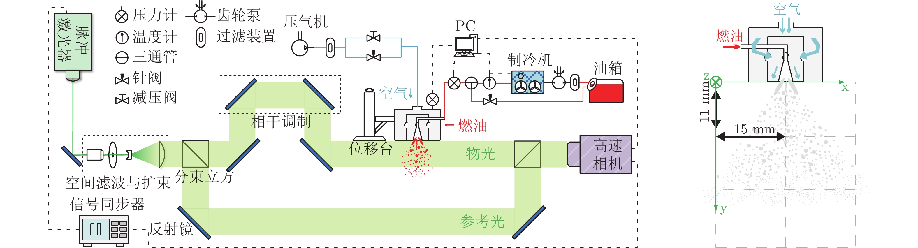
图 1 航空煤油RP-3雾化场脉冲激光离轴全息测试系统示意图
Fig. 1 Experimental setup of pulsed laser off-axis holographic imaging system for atomization measurement of RP-3
![]()
图 2 高速全息标定板重建结果
Fig. 2 Reconstruction result of calibration board in high-speed holography
![]()
图 3 油压0.03 Mpa、油温–20 ℃、气压1 kPa工况雾化场瞬态全息图及其z=276.5 mm处重建截面、三维颗粒场处理结果
Fig. 3 Transient hologram of spray under oil pressure of 0.03 MPa, oil temperature of –20 ℃, and air pressure of 1 kPa, its reconstructed slice image at z=276.5 mm, and 3D droplet distribution field processing results
![]()
图 4 油压0.03 MPa、气压1 kPa下不同油温工况近喷嘴完整雾化场成像
Fig. 4 Joint depth-of-field extended images of near-nozzle atomiza-tion field under different oil temperatures at oil pressure of 0.03 MPa and air pressure of 1 kPa
![]()
图 5 油压0.03 MPa、气压1 kPa、油温28 ℃与–20 ℃时液膜与液丝破碎过程时间分辨成像
Fig. 5 Time-resolved imaging of liquid films and filaments breaking processes at oil temperature of 28 ℃ and –20 ℃ under oil pressure of 0.03 MPa and air pressure of 1 kPa
![]()
图 6 油压0.03 MPa、气压1 kPa下,油温–40 ℃时近喷嘴雾化过程时间分辨成像
Fig. 6 Time-resolved imaging of near-nozzle atomization process at oil temperature of –40 ℃ under oil pressure of 0.03 MPa and air pressure of 1 kPa
![]()
图 7 油压0.03 MPa、气压1 kPa下,不同油温工况近喷嘴雾化场粒径分布统计
Fig. 7 Statistics of droplet size distributions in near-nozzle spray region under different oil temperatures at oil pressure of 0.03 MPa and air pressure of 1 kPa
![]()
图 8 油压0.03 MPa、气压1 kPa下,不同油温工况雾锥截面与空间粒径分布
Fig. 8 Cross-section and spatial droplet size distributions under different oil temperatures at oil pressure of 0.03 MPa and air pressure of 1 kPa
-
[1] 陈光明,王学德,林冰轩. 高空低压低温环境航空发动机燃烧室熄火特性实验[J]. 气体物理,2019,4(5):43-51. DOI: 10.19527/j.cnki.2096-1642.0763 CHEN G M,WANG X D,LIN B X. Experimental study on blowout characteristics of aeroengine combustor under high altitude low pressure and low temperature condition[J]. Physics of Gases,2019,4(5):43-51. doi: 10.19527/j.cnki.2096-1642.0763
[2] LINNE M. Imaging in the optically dense regions of a spray: A review of developing techniques[J]. Progress in Energy and Combustion Science,2013,39(5):403-440. doi: 10.1016/j.pecs.2013.06.001
[3] 张志强,郝毓雅,陈战斌. 航空喷气燃料RP-3运动粘度特性研究[J]. 现代机械,2020(1):38-40. DOI: 10.13667/j.cnki.52-1046/th.2020.01.010 ZHANG Z Q,HAO Y Y,CHEN Z B. Kinematic viscosity characteristics of aviation jet fuel RP-3[J]. Modern Machinery,2020(1):38-40. doi: 10.13667/j.cnki.52-1046/th.2020.01.010
[4] LEE J Y,KIM N H,MIN K D. Measurement of spray character-istics using the background-oriented schlieren technique[J]. Measurement Science and Technology,2013,24(2):025303. doi: 10.1088/0957-0233/24/2/025303
[5] PARRISH S E,ZHANG G M,ZINK R J. Liquid and vapor envelopes of sprays from a multi-hole fuel injector operating under closely-spaced double-injection conditions[J]. SAE International Journal of Engines,2012,5(2):400-414. doi: 10.4271/2012-01-0462
[6] DURONIO F,DE VITA A,ALLOCCA L,et al. Gasoline direct injection engines – A review of latest technologies and trends. Part 1: Spray breakup process[J]. Fuel,2020,265:116948. doi: 10.1016/j.fuel.2019.116948
[7] RUAN C,CHEN F E,CAI W W,et al. Principles of non-intrusive diagnostic techniques and their applications for fundamental studies of combustion instabilities in gas turbine combustors: A brief review[J]. Aerospace Science and Technology,2019,84:585-603. doi: 10.1016/j.ast.2018.10.002
[8] LIU C X,LIU F Q,YANG J H,et al. Experimental investigations of spray generated by a pressure swirl atomi-zer[J]. Journal of the Energy Institute,2019,92(2):210-221. doi: 10.1016/j.joei.2018.01.014
[9] FANSLER T D,PARRISH S E. Spray measurement techno-logy: a review[J]. Measurement Science and Technology,2015,26(1):012002. doi: 10.1088/0957-0233/26/1/012002
[10] PARRISH S E,ZINK R J. Development and application of a high-speed planar laser-induced fluorescence imaging system to evaluate liquid and vapor phases of sprays from a multi-hole diesel fuel injector[J]. Measurement Science and Technology,2013,24(2):025402. doi: 10.1088/0957-0233/24/2/025402
[11] 陈晨,晏至辉,唐志共,等. 气液同轴离心式喷嘴雾化特性试验研究[J]. 江苏科技大学学报(自然科学版),2020,34(6):50-55. DOI: 10.11917/j.issn.1673-4807.2020.06.009 CHEN C,YAN Z H,TANG Z G,et al. Experimental study on spray characteristic of gas-liquid coaxial swirling injectors[J]. Journal of Jiangsu University of Science and Technology(Natural Science Edition),2020,34(6):50-55. doi: 10.11917/j.issn.1673-4807.2020.06.009
[12] HUNG D L S,HARRINGTON D L,GANDHI A H,et al. Gasoline fuel injector spray measurement and characteri-zation – A new SAE J2715 recommended practice[J]. SAE International Journal of Fuels and Lubricants,2008,1(1):534-548. doi: 10.4271/2008-01-1068
[13] ALBRECHT H E, BORYS M, DAMASCHKE N, et al. Laser Doppler and phase Doppler measurement techniques[M]. Berlin, Heidelberg: Springer-Verlag, 2003. doi: 10.1007/978-3-662-05165-8
[14] SHIN J,KIM D,SEO J,et al. Effects of the physical properties of fuel on spray characteristics from a gas turbine nozzle[J]. Energy,2020,205:118090. doi: 10.1016/j.energy.2020.118090
[15] MALARSKI A,SCHÜRER B,SCHMITZ I,et al. Laser sheet dropsizing based on two-dimensional Raman and Mie scattering[J]. Applied Optics,2009,48(10):1853-1860. doi: 10.1364/AO.48.001853
[16] JERMY M C,GREENHALGH D A. Planar dropsizing by elastic and fluorescence scattering in sprays too dense for phase Doppler measurement[J]. Applied Physics B,2000,71(5):703-710. doi: 10.1007/s003400000404
[17] 吴迎春,吴学成,SAWITREE S,等. 全场彩虹技术测量喷雾浓度及粒径分布[J]. 物理学报,2013,62(9):090703. DOI: 10.7498/aps.62.090703 WU Y C,WU X C,SAWITREE S,et al. Concentration and size measurements of sprays with global rainbow techni-que[J]. Acta Physica Sinica,2013,62(9):090703. doi: 10.7498/aps.62.090703
[18] SAENGKAEW S,GODARD G,BLAISOT J B,et al. Experimental analysis of global rainbow technique: sensiti-vity of temperature and size distribution measurements to non-spherical droplets[J]. Experiments in Fluids,2009,47(4-5):839-848. doi: 10.1007/s00348-009-0680-z
[19] LI C,LV Q M,WU Y C,et al. Measurement of transient evaporation of an ethanol droplet stream with phase rain-bow refractometry and high-speed microscopic shadow-graphy[J]. International Journal of Heat and Mass Transfer,2020,146:118843. doi: 10.1016/j.ijheatmasstransfer.2019.118843
[20] COGHE A,COSSALI G E. Quantitative optical techniques for dense sprays investigation: A survey[J]. Optics and Lasers in Engineering,2012,50(1):46-56. doi: 10.1016/j.optlaseng.2011.07.017
[21] HALLS B R, RADKE C D, HEINDEL T J, et al. Charac-terization of three-dimensional dense spray visualization techniques[C]//Proc of the 51st AIAA Aerospace Sciences Meeting including the New Horizons Forum and Aerospace Exposition. 2013. doi: 10.2514/6.2013-477
[22] GUILDENBECHER D R,GAO J,CHEN J,et al. Characterization of drop aerodynamic fragmentation in the bag and sheet-thinning regimes by crossed-beam, two-view, digital in-line holography[J]. International Journal of Multiphase Flow,2017,94:107-122. doi: 10.1016/j.ijmultiphaseflow.2017.04.011
[23] OLINGER D S,SALLAM K A,LIN K C,et al. Digital holographic analysis of the near field of aerated-liquid jets in crossflow[J]. Journal of Propulsion and Power,2014,30(6):1636-1645. doi: 10.2514/1.B34984
[24] LEE J,SALLAM K A,LIN K C,et al. Spray structure in near-injector region of aerated jet in subsonic crossflow[J]. Journal of Propulsion and Power,2009,25(2):258-266. doi: 10.2514/1.36719
[25] ZIAEE A,DANKWART C,MINNITI M,et al. Ultra-short pulsed off-axis digital holography for imaging dynamic targets in highly scattering conditions[J]. Applied Optics,2017,56(13):3736-3743. doi: 10.1364/AO.56.003736
[26] WU Y C,WANG L,LIN W H,et al. Picosecond pulsed digital off-axis holography for near-nozzle droplet size and 3D distribution measurement of a swirl kerosene spray[J]. Fuel,2021,283:119124. doi: 10.1016/j.fuel.2020.119124
[27] 曹娜,徐青,韩长才,等. 基于全息的某型喷嘴燃油雾化三维特性实验研究[J]. 中国激光,2020,47(11):1109001. DOI: 10.3788/CJL202047.1109001 CAO N,XU Q,HAN C C,et al. Study of a centrifugal nozzle spray characterization in space based on off-axis holography[J]. Chinese Journal of Lasers,2020,47(11):1109001. doi: 10.3788/CJL202047.1109001
[28] MINNITI M,ZIAEE A,TROLINGER J D,et al. Ultrashort pulse off-axis digital holography for imaging the core structure of transient sprays[J]. Atomization and Sprays,2018,28(6):565-578. doi: 10.1615/AtomizSpr.2018024340
[29] MINNITI M,ZIAEE A,CURRAN D,et al. Femtosecond digital holography in the near-nozzle region of a dodecane spray[J]. Atomization and Sprays,2019,29(3):251-267. doi: 10.1615/AtomizSpr.2019029444
[30] WU Y C,WU X C,YANG J,et al. Wavelet-based depth-of-field extension, accurate autofocusing, and particle pairing for digital inline particle holography[J]. Applied Optics,2014,53(4):556-564. doi: 10.1364/AO.53.000556

 下载:
下载:


计量
- 文章访问数: 2894
- HTML全文浏览量: 370
- PDF下载量: 64